10
10 ADDITIONAL CABINET
10.1
F
UNCTIONAL DESCRIPTION
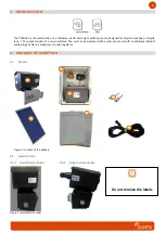
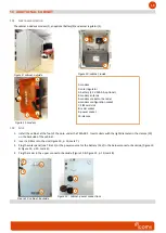
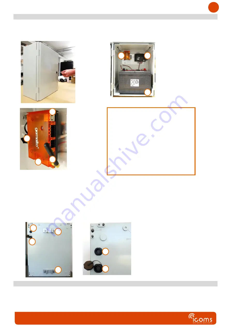
The cabinet includes a modem (1), an optional battery (3) and a solar regulator (2).
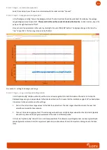
Figure 9: cabinet, outside
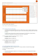
Figure 10: cabinet, inside
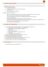
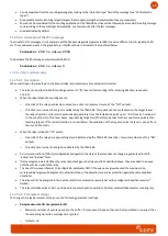
Figure 11: modem
1: modem
2: solar regulator
3: battery (12 V 100 Ah, optional)
4: modem antenna
5: modem socket to the radar
6: modem configuration socket
7: SIM card slot
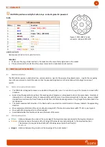
8: radar socket
9: power socket
10: clamps
10.2
S
ETUP
1.
Install the cabinet at the foot of the pole, under the TMA-3B3. Insert collars with the right diameter in the clamps (10)
on the backside of the cabinet.
2.
Insert a SIM card in the slot (Figure 10, p. 10, mark 7).
3.
Plug the solar panel (see Title 11) or the power source for the battery (12 V) in the below connector backside, (Figure 10
& Figure 12, p. 10, mark 9) :
4.
Plug the radar in the upper connector backside (Figure 10 & Figure 12, p. 10, mark 8)
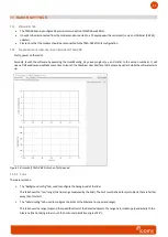
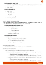
Figure 12: cabinet, backside
Figure 13 : cabinet, power connections
8
9
10
10
1
2
3
4
5
7
6
8
9


