12
11.2.2
Step 1
–
serial communication
Select the serial port your PC uses to communicate with the radar
and click “Connect”
11.2.3
Step 2
–
background configuration
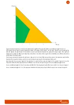
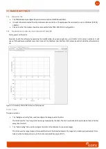
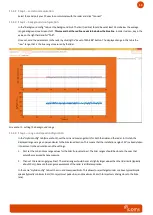
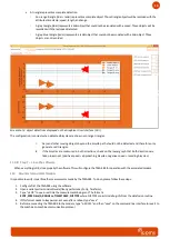
In the “Background config” tab, set the background limit: The
limit (red line) should be set at least 25 cm below the average
range background, see Screenshot 1.
This means that the red line needs to be below the blue line
. In order to do so, key in the
value on the right field and hit “TAB”
.
Once set, send the parameters to the radar by
clicking the “
Save to TMA-3B3
” button. The displayed range in this tab is the
“raw” range, that is the true range measured by the lidar.
Screenshot 1: setting the background range
11.2.4
Step 3
–
range and speed configuration
In
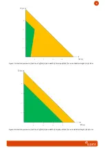
the “Hybrid config” tab
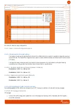
(Screenshot 2), set the min and max range limits for both the lidar and the radar. In this tab, the
displayed ranges are given perpendicular to the bike lane direction. This means that the installation angle of 45° is already taken
into account in the calculations and the settings.
1.
First set the min and max range values for the lidar (turquoise lines). The lidar ranges should be close to the ones that
would be measured by tape measure.
2.
Then set the radar range (grey lines). The radar ranges should be set at slightly larger values than the lidar limits (typically
about 50 cm), because the range measurement of the radar is a little less precise.
In the same “Hybrid config” tab, set the min and max speed limits. This allows to reject targets under or above typical bicyc
le
speeds (typically minimum 8 km/h to reject most pedestrian, and maximum 35 km/h to reject cars driving close to the bike
lane).


