background image


10 

PDX2-057T   DM&P Vortex86DX2 Panel PC with 5.7” VGA TFT LCD 

2 .System Installation 

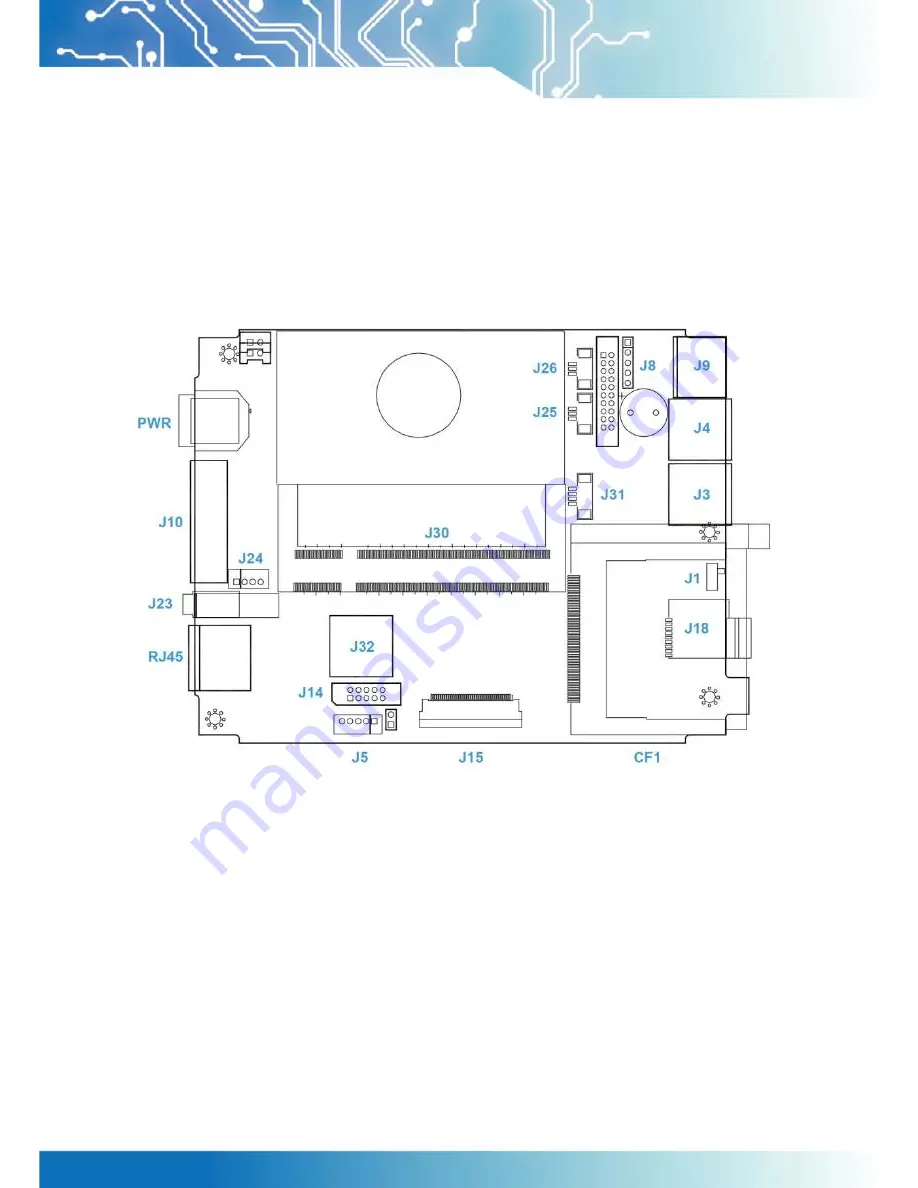
2.1 CPU  Board Outline 


Fig 2-1 PDX2 CPU Board


Summary of Contents for PDX2-057T-5A

Page 1: ...i DM P Vortex86DX2 Panel PC with 5 7 TFT LCD Model PDX2 057T 5A PDX2 057T 8A PDX2 057T 5A 2G PDX2 057T 8A 2G User s Manual Revision 1 1A ...

Page 2: ...i Revision Date Version Description 2016 11 18 Version 1 0 Initial Release 2017 01 10 Version 1 1 Specification correction ...

Page 3: ...ective owners All names mentioned herewith are served for identification purpose only Safety Information Read these Safety instructions carefully Make sure the voltage of the power source is correct before connecting the equipment to the power outlet Do not expose your Panel PC to rain or moisture in order to prevent shock and fire hazard Keep PDX2 057T away from humidity Do not open the cabinet t...

Page 4: ...for TFT LCD Panel 4 1 4 Product Dimension 7 1 5 Ordering Information 8 1 6 Packing List 9 2 System Installation 10 2 1 CPU Board Outline 10 2 2 Connector Summary 11 2 3 Connector Pin Assignments 12 2 4 External I O Overview 14 2 5 External I O Pin Assignment 15 2 6 System Mapping 17 2 7 Watchdog Timer 20 3 Driver Installation 21 3 1 PDX2 057T Development Note 22 3 2 BIOS Default setting 24 Warrant...

Page 5: ...ly minimum power requirement when running at 933MHz and DDR2 memory provides faster data transfer rate By using 5 7 TFT LCD PDX2 057T becomes the perfect choice for a limited budget In additional the integrated 10 100M Ethernet port supplies the communication capability which makes PDX2 057T can be more widely used when running with Linux Windows CE Windows XP Windows 7 Windows Embedded environmen...

Page 6: ...m 30 5u to 512 seconds x 2 sets LAN Integrated 10 100M Ethernet Audio HD Audio Realtek ALC262 CODEC Internal Drives Compact Flash Type I II slot Micro SD slot Optional 1GB or 2GB Flash Memory onboard Optional I O RS 232 422 485 x 1 USB ports Ver2 0 x 2 RJ 45 Port x 1 Mechanical Environment Power Requirement Single Voltage 5VDC PDX2 057T 5A Multi Voltage 8 35VDC PDX2 057T 8A Power Consumption 20W M...

Page 7: ...ons Display Type 5 7 TFT LCD Backlight Unit LED Display Resolution 640 W x 480 H Brightness cd m2 500 nits Contrast Ratio 300 1 Display Color 262 144 Dot Pitch mm 0 06 W x 0 18 H Viewing Angle Vertical 100o Horizontal 140o Backlight Lifetime 50 000 hrs Touchscreen Type Analog Resistive Resolution Continuous Transmittance 80 Controller PS 2 interface Software Driver Linux Win CE Win XP Win 7 Window...

Page 8: ...ura It OK if mura is slight visible through 6 ND filter ELECTRICAL DEFECT BRIGHT DOT A Grade B Grade C Area O Area Total C Area O Area Total Note3 N 0 N 2 N 2 N 2 N 3 N 5 Note2 DARK DOT N 2 N 3 N 3 N 3 N 5 N 8 TOTAL DOT N 4 N 5 N 6 N 8 Note2 TWO ADJACENT DOT N 0 N 1 pair N 1 pair N 1 pair N 1 pair N 1 pair Note4 THREE OR MORE ADJACENT DOT NOT ALLOWED LINE DEFECT NOT ALLOWED 1 One pixel consists of...

Page 9: ...X2 Panel PC with 5 7 VGA TFT LCD Note 1 W Width mm L Length mm N Number φ Average Diameter 1 White Black Spot 2 Polarizer Bubble Fig 1 1 Fig 1 2 Note 2 Bright dot is defined through 6 transmission ND Filter as following Fig 1 3 ...

Page 10: ...defect dots including bright and dart adjacent dot And they will be counted 2 defect dots in total quantity R R G G R G R R G G R G R R G G R G R R G G R G R R G G R G R R G G R G R R Defect Dot Adjacent Dot A B C D 1 The defects that are not defined above and considered to be problem shall be reviewed and discussed by both parties Defects on the Black Matrix out of Display area are not considered...

Page 11: ...7 PDX2 057T DM P Vortex86DX2 Panel PC with 5 7 VGA TFT LCD 1 4 Product Dimension Fig 1 4 Product Dimension ...

Page 12: ...w 2GB DDR2 2USB Line Out LAN COM CF MicroSD Power Adapter PDX2 057T 8A 2G 5 7 Panel PC w 2GB DDR2 2USB Line Out LAN COM CF MicroSD 8 35 DC Support PDX2 057T 5A I 5 7 Panel PC w 1GB DDR2 Wide Temp 2USB Line Out LAN COM CF MicroSD Power Adapter PDX2 057T 8A I 5 7 Panel PC w 1GB DDR2 Wide Temp 2USB Line Out LAN COM CF MicroSD 8 35 DC Support PDX2 057T 5A 2G I 5 7 Panel PC w 2GB DDR2 Wide Temp 2USB Li...

Page 13: ...20W 3PIN PDX2 057T 8A PDX2 057T 8A PDX2 057T 5A 2G PDX2 057T 5A 2G Power 20W 3PIN PDX2 057T 8A 2G PDX2 057T 8A 2G PDX2 057T 5A I PDX2 057T 5A I Power 20W 3PIN PDX2 057T 8A I PDX2 057T 8A I PDX2 057T 5A 2G I PDX2 057T 5A 2G I Power 20W 3PIN PDX2 057T 8A 2G I PDX2 057T 8A 2G I WLAN KIT Optional USB WLAN IPEX KIT WIRELESS ANTENNA 157 WIRELESS CABLE 150MM ...

Page 14: ...10 PDX2 057T DM P Vortex86DX2 Panel PC with 5 7 VGA TFT LCD 2 System Installation 2 1 CPU Board Outline Fig 2 1 PDX2 CPU Board ...

Page 15: ... External D Sub Male Connector 9 pin J14 VGA 2 0mm 10 pin box header 10 pin J18 Micro SD Card Socket Optional Micro SD socket J23 Audio Line Out 1 25mm Phone Jack J24 Audio Mic In 2 0mm 4 pin wafer 4 pin J25 COM3 TX RX 1 25mm 3 pin wafer 3 pin J26 COM4 TX RX 1 25mm 3 pin wafer 3 pin J30 SOM CPU Board Socket SOM CPU Board Socket 200 pin J31 4 Wires Touch connector 1 25mm 4 pin wafer 4 pin J32 USB W...

Page 16: ...D J5 USB Optional Pin Signal Name 1 VCC 2 USBD1 3 USBD1 4 GND 5 GND J8 PS 2 Keyboard Pin Signal Name Pin Signal Name 1 KBCLK 2 KBDAT 3 NC 4 GND 5 VCC J9 PS 2 Keyboard Pin Signal Name Pin Signal Name 1 KBCLK 2 MSCLK 3 GND 4 KBDATA 5 MSDATA 6 VCC 7 GND 8 GND 9 GND J10 COM1 RS232 422 485 Change setting by BIOS Pin Signal Name Pin Signal Name 1 DCD1 422TX RS485 2 RXD1 422TX RS485 3 TXD1 422RX 4 DTR1 4...

Page 17: ...1 MICVREF 2 GND 3 GND 4 MIC IN J25 COM3 TX RX Pin Signal Name 1 GND 2 TXD3 3 RXD3 J26 COM4 TX RX Pin Signal Name 1 GND 2 TXD4 3 RXD4 J31 4 Wires Touch connector Pin Signal Name 1 Y 2 X 3 Y 4 X J32 USB WLAN Optional Pin Signal Name Pin Signal Name 1 VCC 2 USBD2 3 USBD2 4 GND 5 GND 6 GND PWR Power Connector 5A Pin Signal Name 1 5V 2 GND 3 NC 4 GND PWR Power Connector 8A Pin Signal Name 1 8 35V 2 GND...

Page 18: ...l I O Overview PDX2 057T 8A PDX2 057T 8A 2G Fig 2 2 PDX2 057T 8A I O overview PDX2 057T 5A PDX2 057T 5A 2G Fig 2 3 PDX2 057T 5A I O overview Note 1 WLAN is optional 2 COM1 RS232 422 485 is selected by BIOS setting 3 Micro SD Socket is optional Either one of CF or Micro SD ...

Page 19: ...FF Power Connector 5A Pin Signal Name 1 5V 2 GND 3 NC Power Connector 8A Pin Signal Name 1 8 35V 2 GND Audio Line Out Pin Signal Name 1 GND 2 LOUTL 3 Open Touch 4 Open Touch 5 VREFOUT USB Port Pin Signal Name 1 VCC 2 USB0 3 USB0 4 GND 5 GGND 6 GGND PS 2 Keyboard Pin Signal Name 1 KBCLK 2 PMCLK 3 GND 4 KBDAT 5 PMDAT 6 SB5V ...

Page 20: ...J10 COM1 RS232 422 485 Change setting by BIOS Pin Signal Name Pin Signal Name 1 DCD1 422TX RS485 2 RXD1 422TX RS485 3 TXD1 422RX 4 DTR1 422RX 5 GND 6 DSR1 7 RTS1 8 CTS1 9 RI1 RJ45 Pin Signal Name Pin Signal Name 1 FTXD 2 FTXD 3 FRXIN 4 NC 5 NC 6 FRXIN 7 NC 8 NC ...

Page 21: ...A VGA BIOS ROM 000C8000 000CFFFF Boot ROM Enable 000CC000 000CFFFF Console Redirection Enable 000D0000 000DFFFF Expansion ROM Space 000E0000 000EFFFF USB Legacy SCSI ROM Space 000F0000 000FFFFF Motherboard BIOS FEBDE000 FEBDEFFF Standard OpenHCD USB Host Controller FEBDFC00 FEBDFCFF On board Ethernet Adapter I O Mapping I O Address Owner Usage 0000h 000Fh DMA 8237 1 0020h 0021h PIC 8259 1 0022h 00...

Page 22: ...Direction Control 00A0h 00A1h PIC 8259 2 00A8h 00ADh WatchDog1 Control Register 00AEh WatchDog1 Reload Counter 00C0h 00DFh DMA 8237 2 00E0h 00EFh DOS 4G Page Access 0170h 0177h IDE1 IRQ 15 02E8h 02EFh COM4 IRQ 11 02F8h 02FFh COM2 IRQ 3 03E8h 03EFh COM3 IRQ 10 03F6h IDE0 ATAPI Device Control Write only Register 03F8h 03FFh COM1 IRQ 4 0480h 048Fh DMA High Page Register 0490h 0499h Instruction Counte...

Page 23: ...Cascade for IRQ8 15 IRQ3 USB IRQ4 Serial Port 1 IRQ5 USB IRQ6 Unassigned IRQ7 USB IRQ8 Real Time Clock IRQ9 Audio IRQ10 USB IRQ11 Ethernet 10 100M LAN IRQ12 Mouse IRQ13 Math Coprocessor IRQ14 Hard Disk Controller 1 IRQ15 Hard Disk Controller 2 DMA Mapping DMA Description Usage DMA0 DMA1 DMA2 Floppy Disk Controller Reserved DMA3 DMA5 DMA6 DMA7 ...

Page 24: ... 5 7 VGA TFT LCD 2 7 Watchdog Timer There are two watchdog timers in PDX2 057T we also provide DOS Linux and WinCE example for your reference For more technical support please visit http tech icop com tw or download the PDF file dmp com tw tech ...

Page 25: ... and IRQ settings can be done by software with the supplied utility software or it can be set for Plug and Play compatibility The controller supports Half Full Duplex Ethernet function to double channel bandwidth auto media detection AUDIO The ALC262 series are 4 Channel High Definition Audio Codecs with UAA Universal Audio Architecture featuring two 24 bit stereo DACs and three 20 bit stereo ADCs...

Page 26: ...tail information please visit DMP official website 3 1 PDX2 057T Development Note dmp com tw tech Primary IDE Master or Slave 1 Primary IDE Device can be either one of CF or Micro SD and the standard version is for CF slot only 2 CF Slot Primary IDE Master or Slave User can use slide switch in side of CF slot to adjust Master or Slave 3 Micro SD Optional Primary Master only Window CE6 0 and Compac...

Page 27: ...se forced the IDE setting in BIOS to PIO mode before install Linux on PDX2 057T as follows Go to the advanced BIOS setting and make the Onboard IDE Operate Mode is Legacy Mode Windows XP and Windows 7 installation note Please visit technical website to get more information tech icop com tw ...

Page 28: ... system cannot be booted after BIOS changes are made Please follow below procedures in order to restore the CMOS as default setting Press End Key when the power on Press Del to enter the AMI BIOS setup Press F9 to Load Optimized defaults Press F10 to Save configuration changes and exit setup ...

Page 29: ...any damages lost profits lost savings or any other incidental or consequential damage resulting from the use misuse of originality to use this product Vendor will not be liable for any claim made by any other related party Return authorization must be obtained from the vendor before returned merchandise will be accepted Authorization can be obtained by calling or faxing the vendor and requesting a...

Reviews: