3
Icotera A/S, Vibeholms Allé 16, 2605 Brøndby, Denmark - info@icotera.com
Document version: 1.0
User Guide for 1.17.3 Firmware
Product Overview
This chapter provides a general overview of the Icotera i46xx, i68xx, and i485x CPEs, their components, features
and characteristics. For more detailed specifications please refer to their data sheets.
Physical Description
This section describes the physical components of the CPEs, i.e. connectors, LEDs, and buttons.
Connector Panel
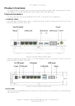
The Icotera i68xx connector panel, shown in the following figure, contains the power port, on/off switch, reset
button, connectors, and LAN status LEDs.
Figure 1. The Icotera i68xx connector panel
The Icotera i4850 connector panel, shown in the following figure, contains the power port, on/off switch, reset
button, connectors, and LAN status LEDs.
Figure 2. The Icotera i4850 connector panel
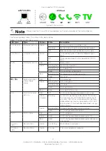
Status LEDs
The status LEDs are divided between the LAN port LEDs and the LEDs on the LED panel that is located between
LAN and POTS ports


