On the other hand, the I-7531 module include two build-in 120
Ω
terminator resistors, user can decide to enable those two terminator resistors
or not.
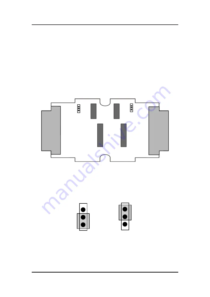
The JP2 of I-7531 is used for adjusting terminal resistor on CAN Port 1,
and the JP3 of I-7531 is used for adjusting terminal resistor on CAN Port 2.
Before adjusting JP2 or JP3 of I-7531, user needs to open the cover of
I-7531 first. Those locations of JP2 and JP3 are shown as following:
Figure7. JP2 and JP3 positions
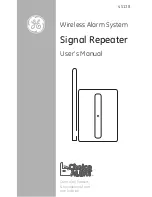
The following connection statuses present the condition if the terminal
resistor is enabled (default) or disabled.
Figure8. Adjustment of Terminator Resistor
Disable
(Deactivate)
Enable
(Activate)
JP2
JP3
CON1
CON2
I-7531 CAN Repeater User Manual (ver. 1.5, 2012/11/22) ------11
ГК
Атлант
Инжиниринг
–
официальный
представитель
в
РФ
и
СНГ
+7(495)109-02-08 sales@bbrc.ru www.bbrc.ru


