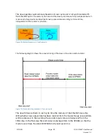
Figure 17: Master-slave cycle in DC mode
Figure 18: Internal slave processing sequence in DC mode
Once the slave receives process data (RxPDOs) from the master the SM2 event is
triggered which causes the firmware to read the data from the ESC memory. The ESC
interrupts the firmware at fixed time interval to process the data received from the
master and write the status data to the ESC memory. Every time when the master fails to
sent process data within the DC cycle time the internal sync error counter is being
increase by three counts. This error counter is being decreased by one count for every
successful DC cycle. Once the error counter reached the maximum count (default 4) a
sync error will be generated and the slave goes into Safe OP mode (Sync Error 0x1C32:20
TRUE). The maximum count value can be set by changing the default value of the "Sync
Error Counter Limit" (0x10F1:02).
Figure 19: Sync error counter limit object
ICP DAS
Page
ECAT-2092T User Manual
Version 1.0
25
Summary of Contents for ECAT-2092T
Page 3: ...Revision Revision Date Description Author 1 18 02 2019 Initial version M K...
Page 50: ...Table 23 Resetting latch register procedure ICP DAS Page ECAT 2092T User Manual Version 1 0 50...
Page 55: ...Step 5 Set the ECAT 2092T back into OP mode ICP DAS Page ECAT 2092T User Manual Version 1 0 55...
Page 70: ......


