H > 2T
Correct
All input signals will pass the filter
T < H < 2T
Incorrect
Some valid input signals will be not pass the input
filter and therefore are not being detected
H < T
Incorrect
The input signal will be filtered
H = the HIGH width of the input signal
T = the period of the filtering clock
Table 10: Low pass filter setting
7.1.5 Compare Trigger Pulse Width
The compare trigger function generates an digital output pulse when the encoder
counter reaches the compare position. Position compare operations and its pulse output
trigger is directly executed by hardware and therefore without any time delay. The pulse
width of the output signal can be set via CoE (0x80n0:0B, n= 0;1). Valid value are 1 to
127.
Pulse Width Setting
Actual Pulse Width
(μSec)
127
(default)
50
110
40
96
30
87
20
80
15
Table 11: Compare trigger pulse output width setting
7.2 Process Data Paramater
7.2.1 Counter
If the ECAT-2092T is being used for reading the encoder counter only then the following
PDOs have to be selected: 0x16n0 and 0x1An0 (n= 0;1). By using TwinCAT the required
PDO can be selected with one click by selecting the "Counter" from the predefined PDO
assignment drop box.
ICP DAS
Page
ECAT-2092T User Manual
Version 1.0
41
Summary of Contents for ECAT-2092T
Page 3: ...Revision Revision Date Description Author 1 18 02 2019 Initial version M K...
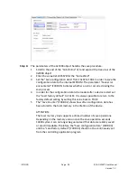
Page 50: ...Table 23 Resetting latch register procedure ICP DAS Page ECAT 2092T User Manual Version 1 0 50...
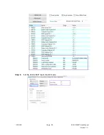
Page 55: ...Step 5 Set the ECAT 2092T back into OP mode ICP DAS Page ECAT 2092T User Manual Version 1 0 55...
Page 70: ......


