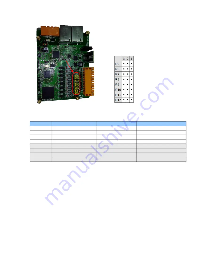
Figure 9: Jumper location
Jumper No
Channel
Jumper position 2-3
Jumper position 1-2
JP5
Encoder input A0
Differential channel
Open collector channel
JP6
Encoder input B0
Differential channel
Open collector channel
JP7
Encoder input Z0 (C0)
Differential channel
Open collector channel
JP8
Extern latch input I0 (HR0)
Differential channel
Open collector channel
JP9
Encoder input A1
Differential channel
Open collector channel
JP10
Encoder input B1
Differential channel
Open collector channel
JP11
Encoder input Z1 (C1)
Differential channel
Open collector channel
JP12
Extern latch input I1 (HR1)
Differential channel
Open collector channel
Table 6: Jumper definitions for the encoder channels
The input levels for the open collector with the internal resistor of 1 K ohm is as follows
Input 12 V:
-
Logic High: 5 V ~ 12 V
-
Logic Low: 0 V ~ 2 V
Input 24V:
-
Logic High: 5 V ~ 24 V
-
Logic Low: 0 V ~ 2 V
4.4 Digital Input Wiring
ICP DAS
Page
ECAT-2092T User Manual
Version 1.0
17
Summary of Contents for ECAT-2092T
Page 3: ...Revision Revision Date Description Author 1 18 02 2019 Initial version M K...
Page 50: ...Table 23 Resetting latch register procedure ICP DAS Page ECAT 2092T User Manual Version 1 0 50...
Page 55: ...Step 5 Set the ECAT 2092T back into OP mode ICP DAS Page ECAT 2092T User Manual Version 1 0 55...
Page 70: ......


