


I-2533 User Manual (ver. 1.1, 2013/05/31) ------4
1.1 Specifications
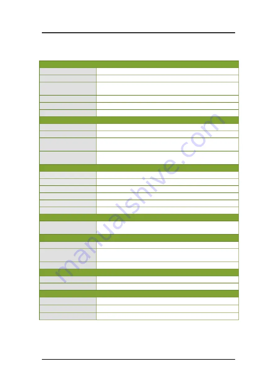
CAN Interface
Connector
Screwed terminal block (CAN_GND, CAN_L, CAN_H)
Baud Rate (bps)
10 k ~ 1 M
Transmission
Distance (m)
Depend on baud rate
Isolation
2500 Vrms
Terminator Resistor
Switch for 120Ω terminator resistor
Specification
ISO-11898-2, CAN 2.0A and CAN 2.0B
Fiber Interface
Connector
ST (Multi-mode)
Wave Length
850 nm
Fiber Cable
50 / 125 μm , 62.5 / 125 μm, 100 / 140 μm
(62.5 / 125μm is recommended)
Transmission
Distance (m)
2 km max (in
62.5 / 125 μm fiber cable)
UART Interface
COM 1
RS-232 (configuration only)
COM 1 Connector
Screwed terminal block (RxD, TxD, GND)
Baud Rate (bps)
115200
Data bit
8
Stop bit
1
Parity
None
LED
Round LED
PWR LED, CAN_Tx LED, CAN_Rx LED, CAN_Err
LED, FB_Err LED
Power
Power supply
Unreg10 ~ +30 V
DC
Protection
Power
reverse
polarity
protection,
Over-voltage
brown-out protection
Power Consumption 3 W
Mechanism
Installation
DIN-Rail
Dimensions
32.3mm x 77.5mm x 99.0mm (W x L x H)
Environment
Operating Temp.
-25 ~ 75
℃
Storage Temp.
-40 ~ 80
℃
Humidity
5 ~ 95% RH, non-condensing


