I-7242D user manual
I-7242D DeviceNet/Modbus RTU Gateway User’s Manual, July 2006, Version 1.1 13/124
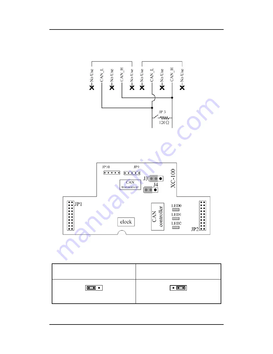
Note that the bypass CAN bus connector is not another CAN channel. It
is designed for connecting to another DeviceNet device conveniently. The
structure of the inside electronic circuit is displayed as figure 2-4.
Figure 2-4 Electronic circuit of CAN bus connector
The jumper-selected termination resistor (J3) is positioned as the figure
2-5. And about the J3 jumper setting, please refer the table 2-4.
Figure2-5 XC100 I/O expansion board LAYOUT
Table 2-4 J3 Jumper Selection
Apply the termination
resistor(120
Ω
)
Don’t apply the termination
resistor
1 2 3
1 2 3


