I-7540D CAN-Ethernet Gateway User’s Manual (Version 1.8, March/2021)
22
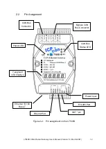
The configuration of CAN port is given as follows:
LED-1: CAN port number
LED-2~5: CAN specification (2.0A or 2.0B)
The connection-client and CAN bus pair connection information are given as
follows:
Group-ID of 5-digit LED: 44444.
LED-1: indicator, can be 0 or 1 or 2 or 3 or 4 or 5.
Indicator 0:
LED-2: ‘P’ for CAN bus pair connection
LED-3: “Enable CAN pair” parameter, 0: Enable, 1: Disable
LED-4: “TCP or UDP” parameter, 0: TCP, 1: UDP.
LED-5: “Server or Client” parameter, 0: act as a server, 1: act as a client
Indicator 1 or 2 or 3 or 4:
The CAN bus pair destination IP information format of I-7540D is given as follows:
LED-2~5: IP
The LED will show Group-ID first, and then show its IP as the above diagram
indicates. If users change can bus pair destination IP and reset the system, the
value shown will change. The default shipping IP = 192.168.255.2
the
LED-show sequence is given as above diagram.
Indicator 5:
LED-2/3: numbers of free sockets are available, default 24.
LED-4/5: numbers of sockets are used by clients, default 0.
If any one client connects to this I-7540D, free-sockets will be decreased and
used-sockets will be increased. If the free-sockets number is reduced to 0, then
no extra client can link to this I-7540D. The default number of free-sockets is 24.
Therefore, the I-7540D allows 24 clients link to it.
Indicator 6:
LED-2~4: “Con.” for connect to server or not
LED-5: 0: not connect to server; 1: already connect to server.

