2.2 Jumper Setting
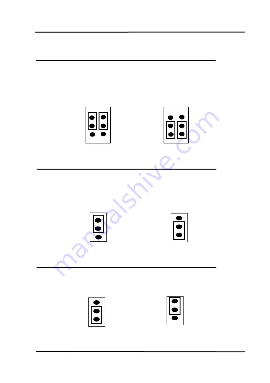
2.2.1 JP1 : A/D Input Type Selection
This jumper is used to select the analog input type. For single-ended inputs,
the use should connect pin1, 3 and pin2, 4. For differential inputs, pin3, 5 and pin4,
6 should be connected.
2.2.2 J1 : D/A Reference Voltage Selection
J1 is used to select the internal D/A output reference voltage. To select the
±
10 V voltage output, the pin 1&2 should be connected. To select the
±
5 V voltage
output, the pin 2&3 should be connected.
2.2.3 D/I Port Setting
(PCI-1202HU/LU/1602U/1602FU only)
This DI ports can be pull-high or pull-low selected by JP2. The location is
given as following:
JP1
Differential
Inputs
6
2
1
5
J1
1
10 Voltage
default
)
±
output (
J1
1
±
5 Voltage
output
JP1
1
5
2
6
Single-Ended
Inputs
(default)
3
2
1
Pull Low
3
2
1
Pull High
JP2
JP2
PCI-1202/1602/1800/1802 Hardware User’s Manual
(
Ver.4.2, Dec/2009, PMH-014-42)---- 20


