background image

Technical support

service@icpdas.com   

P5 

5.


Set device MAC. If you didn’t know the device, you can refer to chapter 4.4.3 on 

user manual. 

6.


Click “Write Setting” to save setting 

Step2.

 Set Computer’s IP 

1.


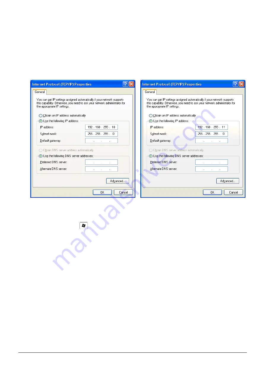
Please set the computer’s IP to 192.168.255.10 and 192.168.255.11. 


Figure 4. set computer IP 

  Step3.

 Internet connection test 

1.


The  Windows(      )  +  R  will  show  you  the  “RUN”  box  where  you  can  type 

commands  to  either  pull  up  a  program.  The  command  line  windows  will  be 

opening after typing “cmd” at the “RUN” box.   

2.


Please execute following command on the command line window. 

Command 1: ping 192.168.255.10 

Command 2: ping 192.168.255.11 

3.


As  shown  in,  the  internet  access  is  working  fine  that  it  should  show  a  similar 

reaction as following figures. 

Summary of Contents for WF-2572

Page 1: ...s in the box In addition to this guide the package includes the following items WF 2572 Antenna ANT 225 05 Screw Driver 1C016 USB Cable CA USB18 1 Appearance No Description 1 Antenna Connector 2 LED Indicator 3 USB Connector 4 Ethernet Connector 5 Power Connector 6 Operating Mode Switch ...

Page 2: ...ON Power Good OFF Power failure Connection Status LINK Blink Always ON Unconnected OFF Connected Communication COMM Blink Data transmission OFF Bus Idle Infrastructure mode Signal strength Signal strength High Signal strength Medium Signal strength Low Unconnected Power PWR Always ON Power Good OFF Power failure Connection Status LINK Blink Always ON Unconnected OFF Connected Communication COMM Bl...

Page 3: ...Step 3 USB port connection WF 2572 supports USB communication for wireless configuration If it does not need to modify the parameter settings this step can be omitted 4 Connection Application Users can use two WF 2572s or one WF 2572 module with the computer that supports wireless network connection structure in the application It can complete the purpose of wireless network connection by this way...

Page 4: ...rface The WF 2572 sets to Infrastructure mode that it connects to the Wi Fi AP Ethernet WF 2572 Infrastructure mode Wi Fi AP PC IP 192 168 255 11 Ethernet PC IP 192 168 255 10 Figure 2 Test Architecture of Infrastructure Step1 Set WF 2572 to Infrastructure mode and Wi Fi parameter 1 2 3 4 5 6 Figure 3 Infrastructure setting step 1 Change Mode to Infrastructure 2 Set AP SSID 3 Set authentication of...

Page 5: ...11 Figure 4 set computer IP Step3 Internet connection test 1 The Windows R will show you the RUN box where you can type commands to either pull up a program The command line windows will be opening after typing cmd at the RUN box 2 Please execute following command on the command line window Command 1 ping 192 168 255 10 Command 2 ping 192 168 255 11 3 As shown in the internet access is working fin...

Page 6: ...2572 sets to the Infrastructure mode Ethernet WF 2572 Limit AP mode Ethernet WF 2572 Infrastructure mode 2 4 5 GHz PC IP 192 168 255 11 PC IP 192 168 255 10 Figure 6 Test Architecture of Limit AP Step1 WF 2572 Limit AP parameter setting 1 Please change the mode to the Limit AP 2 Please select the operation band of WF 2572 3 Please select the AP s Wi Fi channel 4 Please set the AP s SSID 5 Please s...

Page 7: ... shown in Figure 4 the PC s is 192 168 255 10 and 192 168 255 11 Step4 Internet Connection 1 The Windows R will show you the RUN box where you can type commands to either pull up a program The command line windows will be opening after typing cmd at the RUN box 2 Please execute following command on the command line window Command 1 ping 192 168 255 10 Command 2 ping 192 168 255 11 3 As shown in Fi...

Page 8: ...Technical support service icpdas com P8 7 Technical Support Please contact us if you have any questions about products ICP DAS website http www icpdas com Email service icpdas com ...

Reviews: