ICP DAS WISE User Manual
http://wise.icpdas.com
84
completed, continue the configuration of other channel, and after all
channel settings are completed, click “OK” button to save the changes
and return to Modbus RTU Module List.
6.5.6 The Discrete Input Setting of Modbus RTU Module
The Modbus RTU Module Discrete Input Setting page is shown as
follow:
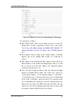
Figure 6-37
:
Modbus RTU module Discrete Input Setting page
The settings are as follow:
Data Model: WISE offers 4 Data Model selections to match the
Modbus RTU module configuration. Please refer to the section
“
6.5.5 The Coil Output Setting of Modbus RTU Module
” for
detailed information. In this case please selects “Discrete Input
(1x)”.
Start Address: Allows setting up the starting address of Discrete
Input (1x) on the Modbus RTU module you would like to retrieve.
Data Number: After finishing the Start Address setting, specify the
Data Number, it is the number of Discrete Input data you would like
to retrieve from the Start Address. The maximum address number of
each data type is
500
.
After finishing the “Start Address” and “Data Number” setting, click
on “Add” button. A new Discrete Input address block will be added
to the Modbus address mapping table. All added address blocks will
be located in sequences staring from the Starting Address (The
address number on the first column of the “Local Address” indicates


