background image

Summary of Contents for 9MPD Series

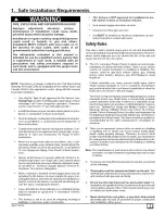
Page 1: ...urrent edition National Fuel Gas Code NFGC ANSI Z223 1 2002 NFPA No 54 2002 In Canada refer tothecurrent edition of the National Standard of Canada Natural Gas and Propane Installation Code NSCNGPIC CSA B149 1 05 Wear safety glasses and work gloves Have fire extinguisher available during start up and adjustment procedures and service calls These instructions cover minimum requirements and conform ...

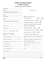
Page 2: ...and Size Fan Time ON Setting Fan Time OFF Setting Manual Gas Shut Off Upstream of Furnace Drip Leg Condensate Drain Connected YES _ YES _ Condensate Drain Trapped YES _ NOE_I NO NO Transition Pressure switch hose relocated for U D H Application YES _ NO _ Blower Speed Checked YES _ NO _ All Electrical Connections Tight YES _ Gas Valve turned ON YES _ NO _ NOE_I Measured Line Pressure When Firing U...

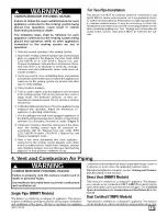
Page 3: ...ally recog nized testing agency in accordance with Underwriters Labora tories Inc Standard for Single and Multiple Station Carbon Monoxide Alarms ANSI UL 2034 or the CSA 6 19 01 Resi dential Carbon Alarming Devices installed and maintained in the building or dwelling concurrently with the gas fired furnace installation see Note below The alarm should be installed as recommended by the alarm manufa...

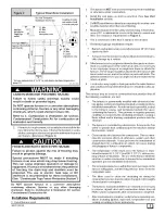
Page 4: ...sert a funnel into the hose and pour four 4 ounces of sani tary type RV antifreeze into the condensate trap Recon nect the 5 8 OD rubber hose to the stub on the vent drain fitting Secure with the hose clamp 2 Disconnect the 3 4 OD rubber hose from the condensate trap Insert a funnel into the hose and and pour four 4 ounces of sanitary type RV antifreeze into the plastic Tran sition box Squeeze the...

Page 5: ...s and ignition sources installed at least 18 457 ram above the floor 8 Furnace must be located or physically protected from pos sible damage by a vehicle If the furnace is to be suspended from the floor joists in a base ment or a crawl space or the rafters in an attic it is necessary to use steel pipe straps or an angle iron frame to attach the furnace These straps should be attached to the furnac...

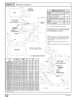
Page 6: ... 0 FRONT combustion air openings in 3 furnace and in structure Required For Service 24 ALL SIDES Of SUPPLY PLENUM 1 SIDES 0 VENT 0 TOP OF FURNACE 1 30 clearancerecommendedfor furnaceremoval Horizontal position Line contact is permissible only between lines formed by intersections of top and two sides of furnace jacket and building joists studs or framing NOTE Evaporator A coil drain pan dimensions...

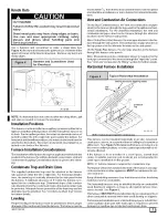
Page 7: ... downflow installations or top to bottom for horizontal installa tions Vent and Combustion Air Connections On the Dual Certified furnace the vent and combustion air pipes attach to the furnace through the top panel for the upflow and hori zontal installations For the downflow installation the vent and combustion air pipes attach to the furnace through the alternate locations on the furnace side pa...

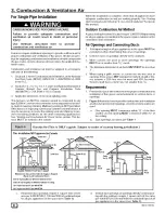
Page 8: ... or marked on grill or lou ver assume a 20 free area for wood and 60 for metal Screens shall have a mesh size not smaller than 1 4 Requirements 1 Provide the space with sufficient air for proper combustion and ventilation of flue gases using horizontal or vertical ducts or openings 2 Figure 6 illustrates how to provide combustion and ventilation air when two permanent openings one inlet and one ou...

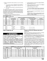
Page 9: ...000 4 000 32 5 Sq In Vertical Total Input 130 000 2 000 65 Sq In Horizontal Standard and Known Air Infiltration Rate Methods NFPA AGA CARBON MONOXIDE POISONING HAZARD Failure to supply adequate combustion air could result in death or personal injury Most homes will require additional air from outdoors for combustion and ventilation A space with at least 50 cubic feet per 1 000 BTUH input rating or...

Page 10: ...ave any means of being closed off Ven tilation openings to outdoors MUST be at least I square inch of free area per 4 000 BTU H of total input rating for all gas ap pliances in the space In spaces that use the Indoor Combustion Air Method in filtration should be adequate to provide air for combustion ventilation and dilution of flue gases However in buildings with unusually tight construction addi...

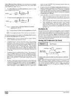
Page 11: ... 1 NFPA 54 and or CSA B149 1 Natural Gas and Propane Installation Code 9 After it has been determined that each appliance connected to the venting system properly vents when tested as outlined above return doors windows exhaust fans fireplace dampers and any other gas fired burning appliance to their previous conditions of use For Two Pipe Installation This furnace can NOT be common vented or conn...

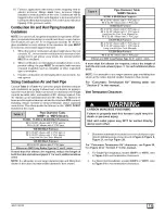
Page 12: ...se of vertical piping is preferred because there will be some moisture in the flue gases that may condense as it leaves the vent pipe See Speciallnstruction ForHorizontal Vents 6 The vertical vent pipe MUST be supported so that no weight is allowed to rest on the combustion blower 7 Exhaust vent piping or air inlet piping diameter MUST NOT be reduced 8 All exhaust vent piping from the furnace to t...

Page 13: ...h 2 PVC pipe or 70 5 90 elbows with 3 PVC pipe 100 000 Btuh Furnace 40 5 90 elbows with 3 PVC pipe or 70 5 90 elbows with 3 PVC pipe Long Vent Kit See Tech Manual 125 000 Btuh Furnace 40 5 90 elbows with 3 PVC pipe Elbows are DWV Long Radius Type for 2 and 3 vents If more than five elbows are required reduce the length of both the inlet and exhaust pipes 5 for each additional elbow used NOTE It is...

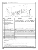
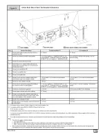
Page 14: ...m on public property 1 In accordance with the current CSA B149 1 Natural Gas and Propane Installation Code 2 In accordance with the current ANSI Z223 1 NFPA 54 National Fuel Gas Cede 18 46 cm above roof surface Permitted only if veranda porch deck or balcony is fully open on a minimum of two sides benealh the floor U S Installation 2 12 30 cm 6 15 cm for appliances _ 10 000 BTUH 3kW 0 23 cm for ap...

Page 15: ...000Btub 3kW and _ 100 000Btuh 30 kW 36 91 cm for appliances 100 000Btuh 30 kW 6 1 83m 12 30 cm 3 91 cm 7 2 13 m U S Installation 2 12 30 cm 4 1 2 m below or to the side of the opening 1 30 cm above the opening 3 91 cm within 15 4 fi m above the meter regulator assembly 4 1 2 m below or to the side of opening 1 30 cm above opening 3 01 cm above if within 10 3m horizontally 3 91 cm 7 2 13 m 1 In acc...

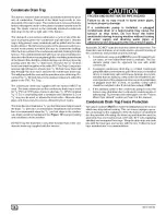
Page 16: ...to the conden sate drain cannot be maintained See Figure 19 for proper routing and installation of the overflow DO NOT trap the drain line in any other location than at the con densate drain trap supplied with the furnace FROZEN AND BURST WATER PIPE HAZARD Failure to do so may result in burst water pipes serious property damage If a condensate pump is installed a plugged condensate drain or a fail...

Page 17: ...charge of Trap Install the black PVC tube connector 3 4 PVC x 1 2 CPVC from loose parts bag as shown in the illustration above Cut the black Drain Tube 5 8 ID in loose parts bag to length to fit between Trap and tube connector through grommet Clamp both ends of the Drain Tube using clamps provided Glue the CPVC street elbow to the Trap using appropriate cleaner and solvent cement Connect the Tee t...

Page 18: ...nect the vent drain to either A standard field supplied 2 PVC tee N9MP1 models or A 2 PVC coupling fastened onto the Drain Tee 9MPD mod els Install Tee trap into bottom of tee Install the 112 CPVC street elbow on discharge of Trap Install the black PVC drain connector 3 4 PVC x 1 2 CPVC from loose parts bag as shown in the illustration above 25 24 81 Cut the black Drain Tube 5 8 ID in loose parts ...

Page 19: ...ugh to exit the cabinet and connect the vent drain to either A standard field supplied 2 PVC tee _9MP1 models or A 2 PVC coupling fastened onto the Drain Tee _9MPD models Install Tee Trap into bottom section of Tee Remove plug from the side of the furnace casing where Drain Tube will exit 44001 102102 Install casing grommet black rubber 5 8 ID grommet in loose parts bag Install the 1 2 CPVC street...

Page 20: ...e 5 8 ID corrugated hose as shown above and fasten the 90 bend end to the Trap and fasten the straight end to the transition drain Secure both connections with clamps Reconnect the 1 2 ID drain hose from the vent drain to the Trap and secure with a clamp In some cases additional length will be required for this hose Use the Black plastic 1 2 OD barbed cou pling and a suitable section of 1 2 ID hos...

Page 21: ...t side of the unit using the 2 screws provided Connect the corrugated Drain Tube from the transition box to the Trap as shown If an extension is required use the black PVC tube connector and the black 5 8 ID Drain Tube in the loose parts bag Cut tube to length Secure all connections with clamps Connect the drain hose from the Vent Drain to the Trap If an ex tension is required use the black 1 2 OD...

Page 22: ... the transition to the Trap Secure connections with clamps Remove the black 1 2 ID Drain Tube from the Drain Tee Install a yellow cap and clamp over the open drain port of the Drain Tee Connect the black 1 2 ID Drain Tube from the Vent Drain to the Trap Secure connections with clamps Connect the 3 16 ID relief tube to the middle port on the Trap If an extension is required use the 3116 OD flexible...

Page 23: ...ct the corrugated hose from the transition to the Trap Secure connections with clamps Connect the black 1 2 ID Drain Tube from the Vent Drain to the Trap If an extension is required use the black 1 2 OD flexible tub ing connector and the black 1 2 ID Drain Tube in the loose parts bag Cut tube to length Secure connections with clamps Connect the 3 16 ID relief tube to the middle port on the Trap If...

Page 24: ... tube as shown in the illustration above Con nect the corrugated hose from the transition to the Trap Secure connections with clamps Connect the black 1 2 ID Drain Tube from the Vent Drain to the Trap If an extension is required use the black 1 2 OD barbed coupling and the black 1 2 ID Drain Tube in the loose parts bag Cut tube to length Secure connections with clamps Connect the 3 16 ID relief tu...

Page 25: ...bove Con nect the corrugated hose from the transition to the Trap Secure connections with clamps Connect the black 1 2 ID Drain Tube from the Vent Drain to the Trap If an extension is required use the 1 2 OD barbed coupling and the black 1 2 ID Drain Tube in the loose parts bag Cut tube to length Secure connections with clamps Connect the 3 16 ID relief tube to the middle port on the Trap If an ex...

Page 26: ... vent and combustion air piping from the furnace to the vent termination Do not cement the pipe joints until the pipe preassembly process is complete Combustion Air Pipe Connection Dual Certified or Direct Vent Install the air intake coupling and gasket to the furnace with the four 4 screws Note The air intake cou piing and gasket ca n be installed to the top panel to the alternate air intake loca...

Page 27: ... to disconnected or leaking vent pipe joints allowing carbon monoxide to enter the living space 1 Cut pipe end square remove ragged edges and burrs Chamfer end of pipe then clean fitting socket and pipe joint of all dirt grease or moisture NOTE Stir the solvent cement frequently while using Use a natu ral bristle brush or the dauber supplied with the cement The prop er brush size is one inch 2 Aft...

Page 28: ...hows the proper installation and clearances for vertical vent termination The vertical roof termination should be sealed with a plumbing roof boot or equivalent flashing The inlet of the intake pipe and end of the exhaust vent must be terminated no less than 12 above the roof or snow accumulation level and 12 away from a vertical wall or other protrusion 2 If the vent system is installed in an exi...

Page 29: ...r Risers 18 Min for Cold Climates Sustained Below 0 F 8 Min Gradeor Snow Level Dimension A is touchinq or 2 maximum separation Rooftop Inlet Vent and Exhaust Air Termination 18 Min for Cold Climates F _ SustainedBelow 0 F 8 Min 20 Max 12 Min Level Exhaust 25 22 43 iii_i_ _ ii ii ii fill 11 i i i i i i i i i i i i i i iiii ii iiiiiiiiiiiiiiiiiiiiiil _i Recommended Alternate Installation for Sustain...

Page 30: ...mination kit must terminate outside the structure and must be installed per the instructions outlined below for vertical or horizontal termina tion Vertical termination is preferred Field supplied pipe and fit tings are required to complete the installation Kit Components KitContents 3 Rain Cap or 2 RainCap 3 Diameter SDR 26 Pipe 19 2 Long or 1 4 Diameter SDR 26 Pipe 37 8 Long t_ 5 i_ 2 Diameter S...

Page 31: ... for NDMP2 Models 50 000 80 000 Btuh Furnaces NAHAOO2CV 35 4 90 elbows with 2 PVC pipe or NAHAOOICV 65 4 90 elbows with 3 PVC pipe 75 000 Btuh Furnace NAHAOO2CV 20 2 90 elbows with 2 PVC pipe or NAHAOO2CV 35 4 90 elbows with 2 PVC pipe Long Vent Kit See Tech Manual or NAHAOOICV 65 4 90 elbows with 3 PVC pipe 100 000 Btuh Furnace NAHAOOICV 35 4 90 elbows with 3 PVC pipe or NAHAOOICV 65 4 90 elbows ...

Page 32: ...idewall Attachment Vent Combustion Air Note Strap Field Supplied Y _ Combustion S 1 max 45 Elbow _ _ c_ FieldSupplied 25 22 02 Securing strap must be field installed to prevent movement of termination kit in side wall 6 Gas Supply and Piping CARBON MONOXIDE POISONING FIRE AND EXPLOSION HAZARD Failure to follow these instructions could result in death personal injury and or property damage Models d...

Page 33: ...ther gas appliance iiiiiiii_i i i i i i _i il i i _i_ _i_i _iii_i_ii_i i i iiii_iii iiiiiiiiiiiii_ii_iii _iiiiiiiiiiiiiiiiii_iiiii_iiiiiiiiiiiiiiiiiiiiiiii_i i_i i i_ii_ii_ii_ii_ii_ii_ii_ Typical Gas Pipingfor Upflow Drip Leg and Union Union should be outside the Gas Pipe Grommet Single Pipe cabinet Manualshut off valveMUST be upstreamof vM_ eUa shut off dripleg union and furnace _ _ _ _ _ __ Use ...

Page 34: ... 55 55 55 55 See Table 10 for High Altitude See Table 11 for High Altitude Supply Pressure ELECTRICAL SHOCK HAZARD Failure to do so could result in death or personal injury Turn OFF power to furnace before changing speed taps 1 2 3 4 Remove the burner compartment door With gas OFF connect manometer to tapped opening on gas valve See Figure 38 Use manometer with a 0 to 15 water column range Turn ga...

Page 35: ...iiiiiiiiiiiiiiiiiiiiiiiiiiiiiiii i i i i i i i i i i i i i i i i i HEATING VALUE at ALTITUDE BTU CU FT 2500 Orifice Size _ _i_i_i_i_i_i_i_i_i_i_i_i_i_ _i_i_i_i_i_i_i_i_i_i_i_i_i_ _i_i_i_i_i_i_i_i_i_i_i_ i i_i_i_i_i_i_i_i_i_i_i_i_i _ _ _ i _ i_ i_ i_ i_ iiiiiiiiiiiiiiiiii _i_i_i ii ii ii ii ii ii ii ii i ii iiiiiiiiiiiiiiiiiiiiiiiiiiii _i_i_i ii i For fuels with different specific gravity consult t...

Page 36: ...NSI Z223 1 2002 N FPA 54 2002 or National Standard Of Canada Natural Gas And Propane Installation Code CSA B149 1 05 NOTE The derating of these furnaces at 2 Natural Gas and 4 Propane Gas has been tested and design certified by CSA o In Canada the input rating must be derated 5 Natural Gas and 10 _ Propane Gas for altitudes of 2 000 to 4 500 above sea level Use the 2001 to 3000 column in Table 8 T...

Page 37: ...e making any electrical connections and ensure a proper ground connection is made before connecting line voltage 44001 102102 FIRE OR EXPLOSION HAZARD Failure to follow the safety warnings exactly could result in death personal injury and or property damage Never test for gas leaks with an open flame Use a commercially available soap solution made specifi cally for the detection of leaks to check ...

Page 38: ... conform to lo cal codes or in the absence of local codes with the latest edition of The National Electric Code ANSI NFPA 70 and or The Canadian Electric Code CSA C22 1 Install wiring in accordance with manufacturer s instructions The wiring MUST have a minimum temperature rating of 105 C Humidifier Electronic Air Cleaner The furnace is wired for humidifier and or electronic air cleaner connection...

Page 39: ...ers are recommended in all branches or in individual ducts to balance system s air flow 4 Non combustible flexible duct connectors are recom mended for return and supply connections to furnace 5 If air return grille is located close to the fan inlet install at least one 90 air turn between fan and inlet grille to reduce noise NOTE To further reduce noise install acoustical air turning vanes and or...

Page 40: ...tallation 1 Position plenum through the floor and set the furnace over the opening in the floor If necessary grout around the base to seal air leaks between the base and the floor Combustible Floor Installation FIRE HAZARD Failure to install unit on noncombustible subbase could result in death personal injury and or property damage Place furnace on noncombustible subbase on downflow applications u...

Page 41: ...imensions Subbases for Combustible Floors Dimensions Subbase for Combustible Floor Dimensions Subbase for Combustible Floors Part Number Furnace Subbase NAHH001SB NAHH002SB NAHH003SB NAHH010SB Subbase for Coil Cabinets NAHH004SB NAHH005SB NAHH006SB NAHH009SB Outside Dimension Base Spacer Side To Side 3 4 5 H J K L 1511 16 283 4 149 16 16 195 16 283 4 183 16 16 22b 16 283 4 2113 16 16 243 4 283 4 2...

Page 42: ...ssure tap and replace plug in gas valve 9 Check for leaks at plug 10 Replace the burner compartment door Main Burner Flame Check FIRE OR EXPLOSION HAZARD Failure to correct hazard could result in death personal injury and or property damage If any sparks odors or unusual noises occur immediately shut OFF power to furnace Check for wiring errors or obstruction to blower Gas Supply Pressure Gas supp...

Page 43: ...tor speed by removing the motor lead from the Heat or Cool terminal and re place it with the desired motor speed lead from the Un used Motor Lead location Connect the wire previously removed from the Heat or Cool terminal to the vacated Unused Motor Lead terminal If the same speed must be used for both heating and cool ing remove the undesired motor speed lead from the Heat or Cool terminal and co...

Page 44: ... tween the Heat and Cont terminals on the furnace control Note There should be only ONE motor lead going to the Heat and Cont terminals FIRE EXPLOSION OR CARBON MONOXIDE HAZARDS Failure to have the furnace inspected and maintained could result in fire explosion death or personal injury It is recommended that the furnace be inspected and serviced on an annual basis before the heating season by a qu...

Page 45: ... demands from furnace control Fan demands from furnace control for heat cool or G will override hard wired speed tap NOTE 3 EAC is NOT active for hard wired mode but IS active for fan demands from furnace control for heat cool and G Heating W Request Heating W Request 24 VAC signal applied to W terminal of FCB Inducer motor turns on and the pressure switch es close s Following a 15 second prepurge...

Page 46: ...s off fuse is open Heartbeat Normal operation or no previous Diagnostic Code QN SOLID Soft Lockout Furnace Control Error 1 hr delay If code repeats immediately following power reset then replace control 1 Flash Not used 2 Flashes Pressure switch es closed when should be open 3 Flashes Pressure switch open when should be closed 4 Flashes Limit or roll out switch open less than 2 minutes 5 Flashes F...

Page 47: ...B12C1 N9MP1075B12C1 N9MP1080F16C1 N9MP1100F14C1 N9MP1100J 20Cl N9MP1125J20C1 or Two Pipe N9MP2050B12C1 N9MP2075B12C1 N9MP2080F16C1 N9MP2100F14C1 N9MP2100J20C1 N9MP2125J20C1 or Dual Certified 9MPD050F12C1 9MPD075F12C1 9M PD080J 16Cl 9MPD100J14C1 9MPD100J20Cl 9MPD125L20C1 Denotes Brand Save This Manual For Future Reference 440 01 102102 _ ...

Page 48: ...C Transition Switch Pressure Close WC Transition Switch Pressure Open WC High Altitude Pressure Sw Part No Blower Switch Pressure Close WC Blower Switch Pressure Open WC Transition Switch Pressure Close WC Transition Switch Pressure Open WC Long Vent Kit Part No Pressure Switch Part No Blower Switch Pressure Close WC Blower Switch Pressure Open WC Transition Switch Pressure Close WC Transition Swi...

Page 49: ... Open WC High Altitude Pressure Sw Part No Blower Switch Pressure Close WC Blower Switch Pressure Open WC Transition Switch Pressure Close WC Transition Switch Pressure Open WC Long Vent Kit Part No Pressure Switch Part No Blower Switch Pressure Close WC Blower Switch Pressure Open WC Transition Switch Pressure Close WC Transition Switch Pressure Open WC High Altitude Long Vent Kit Part No Pressur...

Page 50: ...sure Close WC Transition Switch Pressure Open WC High Altitude Pressure Sw Part No Blower Switch Pressure Close WC Blower Switch Pressure Open WC Transition Switch Pressure Close WC Transition Switch Pressure Open WC Long Vent Kit Part No Pressure Switch Part No Blower Switch Pressure Close WC Blower Switch Pressure Open WC Transition Switch Pressure Close WC Transition Switch Pressure Open WC Hig...

Page 51: ...3 636 840 1076 1263 O _ o 0 4 595 812 1031 1202 _ _ 0 5 546 766 987 1148 o 0 6 490 702 889 1077 0 7 630 821 989 _J 0 8 550 750 914 0 9 462 676 833 1 0 601 747 11 9MPD080J16 1 Denotes Brand Speed Low Med L Med H Hi lap 0 1 823 1109 1527 1850 0 2 795 1087 1482 1791 0 3 747 1056 1426 1720 O 0 4 677 1016 1382 1648 0 5 617 970 1317 1575 _ _ 0 6 544 854 1245 1485 _ 0 7 763 1154 1401 0 8 652 1043 1284 X ...

Page 52: ...4 x w 0 9 1266 1428 1515 1 0 1351 gMPD125L20 2 Denotes Brand Speed Low Med L Med H Hi Tap 0 1 1720 1910 2127 2315 0 2 1686 1881 2087 2268 0 3 1644 1833 2024 2201 9 _ 0 4 1600 1777 1961 2131 _o _ 0 5 1533 1720 1891 2029 0 6 1494 1647 1804 1948 0 7 1413 1571 1708 1820 w 0 8 1306 1470 1604 1730 0 9 1349 1484 1614 1 0 1328 1430 II N9MP1125J20 N9MP2125J20 2 4 Speed Low Med L Med H Hi Tap 0 1 1720 1910 ...

Page 53: ... _ M 24VAC BLACK BK P SS SWITCH I _unc on ox B_AC 1 BLUE BL I LL _ _P_ SD0 O LY 3 This wire must be connected to furnace sheet metal for control tOprove flame ORANGE MHI BROWN BR I_ I P18 NOTE 8 _ 4 Symbois are eiectrical representation only BLUE MLO GREENMELLOW GRNIY _ i _ _ _ ORANGE O I GAS I U __ U 5 Solid lines inside circuit board are printed circuit board traces and are RED LO RED R I VALVE ...

Page 54: ...YY LL ZZ WW 15 12 11 Representative drawing only some models may vary in appearance DD 17 16 GG 14 f 18 FF CC 2 Y X Q D 7 HH lO M 25 24 75a 3 i ...

Page 55: ...Blower 1013011 1 1 1 1 1011420 1 1 1 1 1 1 1 1 6 Transformer 1172810 1 1 1 1 1 1 1 1 1 1 1 1 7 Capacitor 10Mfd 370V 1171729 1 1 1 1 7 SMfd 370V 1171728 1 1 1 1 40Mfd 370V 1171982 1 1 1 1 8 Control 1172550 1 1 1 1 1 1 1 1 1 1 1 1 9 Switch Interlock 1171981 1 1 1 1 1 1 1 1 1 1 1 1 10 Switch Pressure 1013802 1 1 1 1 1 1013811 1 1 1013801 1 1 1 1013166 1 1 11 Blower Exhaust Jakel 1172823 1 1 1 1 1 1 1...

Page 56: ...wer 1172885 1 1 1 1 1172969 1 1 1 1 1 1 1 1 J Panel BlowerCutoff 721020013 1 1 1 1 721020008 1 1 1 1 1 1 1 1 K Hange_Blower 1012328 2 2 2 2 2 2 2 2 2 2 2 2 L Doo Blower 1172992 1 1 1172994 1 1 1172996 1 1 1172991 1 1 1172993 1 1 1172995 1 1 M Bracket DoorFiller 1172231 1 1 1 1 1172232 1 1 1 1 1172233 1 1 1 1 N Doo Front 1013789 1 1 1013790 1 1 1013791 1 1 1013210 1 1 1013211 1 1 1013212 1 1 O Stra...

Page 57: ...2 2 2 2 2 2 2 2 2 2 2 2 HH Bracket ControlMounting 1172845 1 1 1 1 1 1 1 1 1 1 1 1 JJ Tube Sensor 1172240 1 1 1 1 1 1 1 1 1 1 1172238 1 1 1172241 1 1 KK Trap Drain Assembly 1171917 1 1 1 1 1 1 1 1 1 1 1 1 LL Sightglass 1012756 1 1 1 1 1 1 1 1 1 1 1 1 QQ Gasket Trap 1013701 1 1 1 1 1 1 1 1 1 1 1 1 RR Bracket Trap 1171986 1 1 1 1 1 1 1 1 1 1 1 1 SS Gasket Trap Bracket 1172000 1 1 1 1 1 1 1171987 1 1...

Page 58: ... 314 X 1 2 1171995 1 1 1 1 1 1 1 1 1 1 1 1 Plate CoverTrap 1171999 1 1 1 1 1 1 1 1 1 1 1 1 Gasket Trap Bracket 1171987 1 1 1 1 1 1 1 1 1 1 1 1 Elbow 1 2 CPVCStreet 1171996 1 1 1 1 1 1 1 1 1 1 1 1 Grommet Casing 1171997 1 1 1 1 1 1 1 1 1 1 1 1 Tube Releif Ext 1172239 1 1 1 1 1 1 1 1 1 1 1 1 Connector ReleifTube 1171998 1 1 1 1 1 1 1 1 1 1 1 1 Gasket CoverPlate 1172000 1 1 1 1 1 1 1 1 1 1 1 1 Cap Dr...

Page 59: ...r 14 Igniter 15 Orifice Burner 42 Nat 44 Nat 16 Switch Limit Rollout 17 BurnerAssembly 18 Switch Limit Main 1012850 1012854 1012858 1012862 1013762 1013763 1013765 1013767 1172488 1172487 1172489 1014824 1014822 1014823 1013011 1011420 1172810 1171928 1171929 1171982 1172550 1171981 1013802 1013812 1013166 1172823 1172824 1172821 1172827 1172553 1011351 1011352 1013102 1172884 1172965 1172966 1172...

Page 60: ...328 1173015 1173016 1173082 1173009 1173010 1173072 1173012 1173013 1173075 1172232 050F120 1 1 1 1 1 2 1 078F120 1 1 2 1 080J160 I I 1 2 1 100J14C I I 1 2 1 100J2OC 1 1 1 2 1 Door Front Tstaronly Tstaronly Tstaronly CmakerlKeepriteonly CmakerlKeepriteonly CmakerlKeepriteonly HeillArcoonly HeillArcoonly HeillArcoonly Clamp Capacitor TransitionAssembly Gasket Blower Board Insulating Box Collector G...

Page 61: ...oupling Air Intake Gasket Air Intake Clamp Hose314 Clamp Hose5 8 Coupling Discharge ClampHose Grommet Vent Bushing StrainRelief Grommet Vinyl gas Inlet Harness Wire Part Number 1012350 1172860 1012276 1012277 1012278 1012279 1172847 1172849 1172850 1012338 1012339 1012340 1013702 1013703 1013704 1012377 1012532 1172845 1172240 1172238 1172241 1171917 1013235 1013236 1013701 1171986 1171987 1172245...

Page 62: ...ctor 314 X I12 Elbow I12 CPVCStreet Grommet Casing Tube Relief Ext Connector ReliefTube Plate Cover Gasket Cover Plate Cap Drain Tee Clamp TeeCap InstallationManual User sManual Pan Number 1171916 1171991 1171992 1171993 1171994 1171995 1171996 1171997 1172239 1171998 1171999 1172000 1172255 1172256 44001102102 44102201100 050F12C 1 1 2 1 1 1 1 1 1 1 1 1 1 1 1 1 075F12C I I 2 I I I I I I I I I I I...

Reviews: