Two- Stage Multi Position Furnace
Service Manual
14
440 08 2002 02
DUAL CERTIFIED
models require a combustion air inlet
pipe to bring in all air for combustion from outside the struc-
ture
only
when installed as a Direct Vent Furnace (I.E. Two
Pipe Installation)
Consult the appropriate Venting tables and/or piping chart
for the model (series) you are servicing.
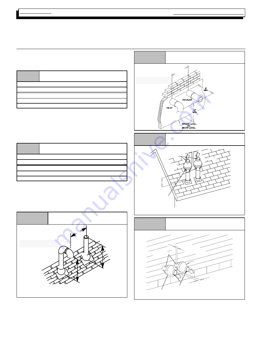
16. STANDARD VENT TERMINATION
Vent/Combustion Air Piping Charts
Single Piping Chart
Table 4
Pipe Diameter Table
Single Piping ONLY
50,000 & 75,000 Btuh Furnaces
40
¢
& (5) 90
°
elbows with 2
²
PVC pipe
100,000 & 125,000 Btuh Furnace
40
¢
& (5) 90
°
elbows with 3
²
PVC pipe
Elbows are DWV Long Radius Type for 2
²
and 3
²
vents.
If more than five elbows are required, reduce the length of both
the inlet and exhaust pipes 5
¢
for each additional elbow used.
NOTE:
It is allowable to use larger diameter pipe and fitting than
shown in the tables but
not
smaller diameters than shown.
Dual Piping Chart
Table 5
Pipe Diameter Table
Dual Piping ONLY
50,000 & 75,000 Btuh Furnaces
40
¢
& (5) 90
°
elbows with 2
²
PVC pipe
100,000 & 125,000 Btuh Furnace
40
¢
& (5) 90
°
elbows with 3
²
PVC pipe
Elbows are DWV Long Radius Type for 2
²
and 3
²
vents.
If more than five elbows are required, reduce the length of both
the inlet and exhaust pipes 5
¢
(1.5m) for each additional elbow
used.
*
Feet of pipe is whichever pipe run is the longest, either inlet
or
outlet side.
Figure 15
Standard Termination
Rooftop Termination
25--00--06
A
A
B
A = 12
²
Above roof or snow accumulation level
B = 8
²
Min., 20
¢
Maximum, except in areas with extreme
cold temperatures (sustained below 0
°
F), the 18
²
Min.
Inlet is optional on
Dual Certified models
Inlet is optional on
Dual Certified models
Figure 16
Sidewall Termination 12
²
or More
Above Snow Level or Grade Level
8
²
*
MIN.
20’
MAX
*18
²
Minimum for cold climates
(substained below 0
°
F)
25--00--05F
Figure 17
Concentric Vent and Combustion--
Air Roof Termination
“A”
Combustion
Air
Exhaust
12
²²²²
Min. Grade
or Snow Level
Dimension “A” is touching or 2
²
maximum separation.
Figure 18
Concentric Vent and Combustion--
Air Sidewall Termination
“A”
Vent
Dimension “A” is touching or 2
²
maximum separation.
25--22--02d
Vent
Combustion Air
1
²²²²
Maximum
(TYP.)
Exhaust


