Two- Stage Multi Position Furnace
Service Manual
27
440 08 2002 02
2 SPEED MODELS - P.S.C. MOTOR
HEATING SPEEDS
Should it be necessary to change blower speeds to obtain
proper temperature rise on either (or both) High fire, and/or
Low Fire, Simply take the appropriate speed tap wire, and
plug it on to the terminal marked “HEAT HIGH” or “HEAT
LOW” respectively on the HONEYWELL ST9162A control.
Figure 37
2 Speed Models
Blower Speed Taps
Wire Color
Motor Speed
Black
High
Orange
Medium--High
Blue
Medium--Low
Red
Low
COOLING SPEED
When the proper speed has been determined, simply plug
it on to the terminal marked ”COOL” on the HONEYWELL
ST9162A control.
“M1 ” & “M2 ” TERMINALS
There are two (2) terminals (marked “M1” & “M2”) on the
HONEYWELL ST9162A control which have no internal
connection to the control. Their purpose is to provide a
place to connect, or “PARK” any “UNUSED” speed tap
wires (P.S.C. motors ONLY) to keep them out of the way
and prevent them from shorting out against the furnace
casing, or each other.
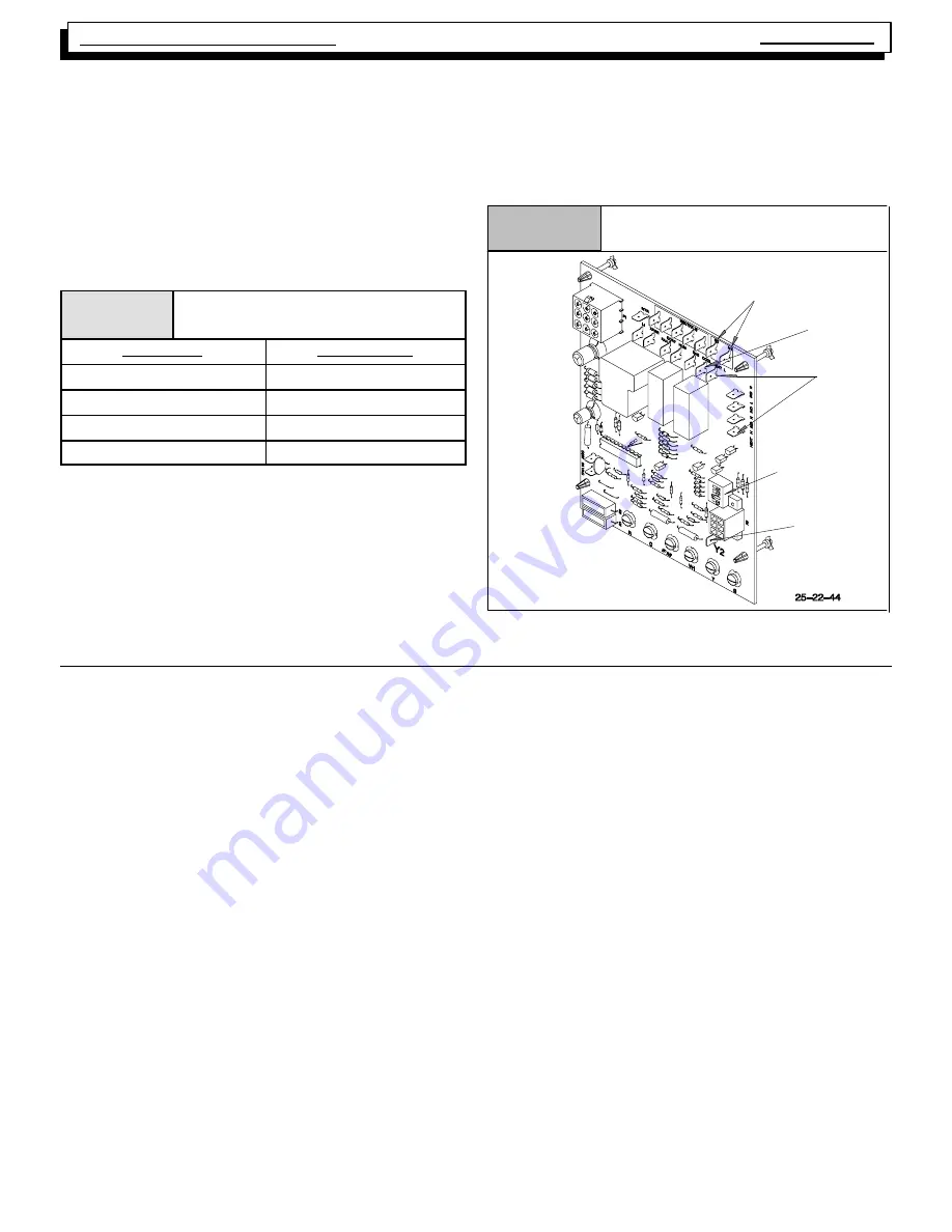
Figure 38
Honeywell ST9162
Dip Switch
Y2 Terminal
M1 & M2 Terminals
Cooling
Terminal
Heating
Terminals
27. BLOWER ROTATION
·
The startup of a furnace will involve a cycle or two of the fur-
nace to properly prime the condensate trap with water. Until
the trap is fully primed, some condensate will be pulled into
the combustion blower. The furnace may cycle on the pres-
sure switch connected to the plastic transition box due to con-
densate buildup. After the trap is primed, the condensate will
start draining from the furnace. The combustion blower will
clear out any remaining condensate in the blower housing
through the vent fitting downstream of the blower. Note that
the condensate trap can also be primed by pouring water into
the vent drain side of the trap. Remove the small plastic cap
and clamps from the unused drain stub on the vent drain side
of the condensate trap. Connect a section of the
5
/
8
²
OD hose
with a funnel to the drain stub and pour eight (8) ounces of wa-
ter into the trap. Remove the hose and replace the plastic cap
and clamp. This will prime both the vent and the transition
sides of the trap.
·
The startup of a furnace will have “milky or oily”. looking con-
densate coming from the furnace. This is residual drawing
lube in the secondary heat exchanger that is being washed
out by the condensate. The condensate will clear up as the
furnace operates. Poisonous carbon monoxide gas hazard.
·
The use of a vent tee at the outlet of the condensate trap is not
required if the condensate drain line from the trap to the open
drain is properly sloped (
1
/
4
²
per foot downward slope). Do
not trap the drain line in any other location than at the conden-
sate trap.
·
The combustion blowers and blower gaskets are different on
some of the furnace models. There are two part numbers of
the combustion blower for the 2--stage furnace models. (See
the
Tech. Manual
for the correct part number for the furnace.)
Besides the part number difference, the 50M, 75M and 100M
BTUH models use the shaded pole motor version with the
1
7
/
8
²
diameter back plate with a raised lip. The blower gasket
is approximately 2
3
/
4
²
outside diameter and is positioned into
the recessed opening in the transition. The 125M BTUH mod-
els use the PSC motor version with the 2
²
diameter back plate
with no lip. The blower gasket is approximately 3
1
/
4
²
outside
diameter and is positioned on the flat surface of the transition.
A mismatch of blower backplated and/or gaskets can cause
the furnace to cycle on the pressure switch or to not operate.
This could be misread as a condensate drainage problem.


