3
PART 1
INSTALLATION
FOR YOUR SAFETY
DO NOT STORE OR USE GASOLINE OR OTHER
FLAMMABLE VAPOURS AND LIQUIDS IN THE
VICINITY OF THIS OR ANY OTHER APPLIANCE.
DO NOT ATTEMPT TO START THE BURNER WHEN
EXCESS OIL HAS ACCUMULATED, WHEN THE
FURNACE IS FULL OF VAPOUR OR WHEN THE
COMBUSTION CHAMBER IS VERY HOT.
1.1)
DANGER, WARNING AND CAUTION
The words DANGER, WARNING and CAUTION are used to
identify the levels of seriousness of certain hazards. It is
important that you understand their meaning. You will notice
these words in the manual as follows:
DANGER
Immediate hazards which
WILL
result in death or
serious bodily and/or material damage.
WARNING
Hazards or unsafe practices which CAN result
in death or serious bodily and/or material
damage.
CAUTION
Hazards or unsafe practices which
CAN
result in
minor bodily and/or material damage.
WARNING
For use with grade 2 Fuel Oil maximum. Do
not
use gasoline, crankcase oil or any oil containing
gasoline!
WARNING
Never burn garbage or paper in the heating
system and never leave rags or paper around the
unit.
CAUTION
These instructions are intended for use by
qualified personnel having been trained in
installing this type of furnace. Installation of this
furnace by an unqualified person may lead to
equipment damage and/or hazardous conditions,
which may lead to bodily harm.
Model cross-reference table
Models
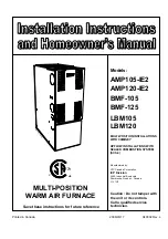
AMP105-IE2 BMF-105 LBM105
AMP120-IE2 BMF-125 LBM120
IMPORTANT:
Refer to the SCS-4 Instruction Manual
for Sealed Combustion Systems (SCS). The appliance
must be installed in an upflow position when used with
an SCS.
Summary of Contents for AMP105-IE2
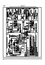
Page 20: ...FIGURE 12 1 Diagramme lectrique AMP LBM BMF 075 090 et 105 br leur Beckett 21...
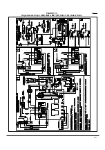
Page 21: ...FIGURE 12 2 Diagramme lectrique AMP LBM BMF 120 140 et 155 br leur Beckett 22...
Page 22: ...FIGURE 12 3 Diagramme lectrique AMP LBM BMF 075 090 et 105 br leur Riello 23...
Page 23: ...FIGURE 12 4 Diagramme lectrique AMP LBM BMF 120 140 et 155 br leur Riello 24...
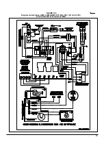
Page 26: ...FIGURE 12 7 Diagramme lectrique AMP LBM BMF 075 090 et 105 br leur B SCS 27...
Page 27: ...FIGURE 12 8 Diagramme lectrique AMP LBM BMF 120 140 et 155 br leur B SCS 28...
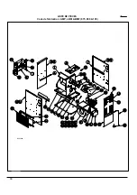
Page 28: ...29 COMPOSANTES ET PI CES DE REMPLACEMENT...
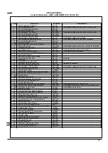
Page 29: ...LISTE DE PI CES Code de fabrication AMP LBM BMF 075 090 105 30 B50058A...
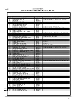
Page 31: ...LISTE DE PI CES Code de fabrication AMP LBM BMF 120 140 155 32 50062A...
Page 51: ...19 FIGURE 12 1 Wiring diagram AMP LBM BMF 075 090 105 Beckett burner...
Page 52: ...20 FIGURE 12 2 Wiring diagram AMP LBM BMF 120 140 155 Beckett burner...
Page 53: ...21 FIGURE 12 3 Wiring diagram AMP LBM BMF 075 090 105 Riello burner...
Page 54: ...22 FIGURE 12 4 Wiring diagram AMP LBM BMF 120 140 155 Riello burner...
Page 57: ...FIGURE 12 7 Wiring diagram AMP LBM BMF 075 090 105 B SCS burner 25...
Page 58: ...FIGURE 12 8 Wiring diagram AMP LBM BMF 120 140 155 B SCS burner 26...
Page 59: ...27 COMPONENTS AND REPLACEMENT PARTS...
Page 60: ...PARTS LIST Model AMP LBM BMF 075 090 105 28 B50058A...
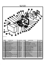
Page 62: ...PARTS LIST Model AMP LBM BMF 120 140 155 30 B50062A...

