4
IMPORTANT:
All local and national code require-
ments governing the installation of oil burning
equipment, wiring and flue connections must be
followed. Some of the codes that may be applicable
are:
CSA B139
INSTALLATION CODE FOR OIL
BURNING
EQUIPMENT
ANSI/NFPA 31
INSTALLATION OF OIL BURNING
EQUIPMENT
ANSI/NFPA 90B WARM AIR HEATING AND AIR
CONDITIONING
SYSTEMS
ANSI/NFPA 211 CHIMNEYS, FIREPLACES, VENTS
AND SOLID FUEL BURNING
APPLIANCES
ANSI/NFPA 70
NATIONAL ELECTRICAL CODE
CSA C22.2 No.3 CANADIAN ELECTRICAL CODE
Only the latest issues of the above codes should be
used, and are available from either:
The National Fire Protection Agency
1 Batterymarch Park
Quincy, MA 02269
or
The Canadian Standards Association
178 Rexdale Blvd.
Rexdale, Ontario M9W 1R3
1.2) GENERAL
This central heating unit is a true multi-position unit, in that it
can operate in four different configurations
when used with
a chimney
, i.e., upflow, counter flow (downflow), and
horizontal (both left-to-right and right-to-left airflow).
Very few modifications are required during installation, to
change the furnace from one configuration to another. The
furnace is shipped in the upflow configuration; however,
instructions on how to change to the other configurations are
included in this manual.
CAUTION
This unit can only be installed in an upflow configuration if a
Sealed Combustion System (SCS) is used with it.
The furnace is shipped complete with burner and controls. It
requires a 115VAC line voltage connection to the control
panel, thermostat hook-up as shown on the wiring diagram,
one or more oil line connections, suitable ductwork and
connection to a properly sized vent.
The air handling capacity of this furnace is designed for
cooling as well. Refer to Table 4 for the expected airflow at
various external static pressures.
1.3) LOCATION
The unit must be installed in a location where the ambient
and return air temperature is over 15°C (60°F).
WARNING
This furnace is not watertight and is not designed
for outdoor installation. This furnace shall be
installed in such a manner as to protect the
electrical components from water. Outdoor
installation will lead to a hazardous electrical
condition and to premature furnace failure.
CAUTION
If this furnace is installed in an attic, it is important
to keep insulation at least 0.3 m (12") away from
any furnace openings. Some types of insulating
material may be combustible.
This furnace is approved for reduced clearances to
combustible construction. Therefore, it may be installed in a
closet or similar enclosure. As this unit may be installed as
an upflow, counter flow, or horizontal furnace, it may be
located in a basement, on the same level as the area to be
heated, suspended, or in a crawlspace. In any case, the unit
should always be installed level.
In a basement, or when installed on the floor (as in a
crawlspace), it is recommended that the unit be installed on
a concrete pad that is 25.4 mm to 50.8 mm (1
"
to 2
")
thick.
When installed in the counter flow position, this furnace must
not be installed on combustible flooring, unless the approved
sub-base is used (Model # DFB-101). Since the flue pipe is
in counter flow position, be sure that the clearances from the
flue pipe to combustible construction are maintained. Also, it
is recommended to use the flue pipe protection kit FPG-101
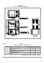
or FPG-102. Refer to Figure 1 and the installation
instructions included with the kit.
FIGURE 1
DNS-0278 Rev. A
Summary of Contents for AMP105-IE2
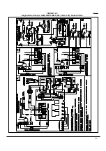
Page 20: ...FIGURE 12 1 Diagramme lectrique AMP LBM BMF 075 090 et 105 br leur Beckett 21...
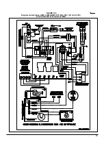
Page 21: ...FIGURE 12 2 Diagramme lectrique AMP LBM BMF 120 140 et 155 br leur Beckett 22...
Page 22: ...FIGURE 12 3 Diagramme lectrique AMP LBM BMF 075 090 et 105 br leur Riello 23...
Page 23: ...FIGURE 12 4 Diagramme lectrique AMP LBM BMF 120 140 et 155 br leur Riello 24...
Page 26: ...FIGURE 12 7 Diagramme lectrique AMP LBM BMF 075 090 et 105 br leur B SCS 27...
Page 27: ...FIGURE 12 8 Diagramme lectrique AMP LBM BMF 120 140 et 155 br leur B SCS 28...
Page 28: ...29 COMPOSANTES ET PI CES DE REMPLACEMENT...
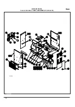
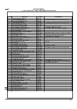
Page 29: ...LISTE DE PI CES Code de fabrication AMP LBM BMF 075 090 105 30 B50058A...
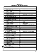
Page 31: ...LISTE DE PI CES Code de fabrication AMP LBM BMF 120 140 155 32 50062A...
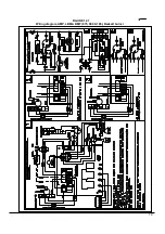
Page 51: ...19 FIGURE 12 1 Wiring diagram AMP LBM BMF 075 090 105 Beckett burner...
Page 52: ...20 FIGURE 12 2 Wiring diagram AMP LBM BMF 120 140 155 Beckett burner...
Page 53: ...21 FIGURE 12 3 Wiring diagram AMP LBM BMF 075 090 105 Riello burner...
Page 54: ...22 FIGURE 12 4 Wiring diagram AMP LBM BMF 120 140 155 Riello burner...
Page 57: ...FIGURE 12 7 Wiring diagram AMP LBM BMF 075 090 105 B SCS burner 25...
Page 58: ...FIGURE 12 8 Wiring diagram AMP LBM BMF 120 140 155 B SCS burner 26...
Page 59: ...27 COMPONENTS AND REPLACEMENT PARTS...
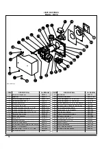
Page 60: ...PARTS LIST Model AMP LBM BMF 075 090 105 28 B50058A...
Page 62: ...PARTS LIST Model AMP LBM BMF 120 140 155 30 B50062A...

