441 01 2314 06
Specifications are subject to change without notice.
21
Sub-base for Combustible Floors- Downflow Coil
Adapter Box
The subbase for combustible floors is required when a downflow
furnace,
used with a downflow coil box
, is set on combustible
flooring.
NOTE:
Supply opening is 3
7
/
8
″
(98.4mm) from the rear of the fur-
nace. Therefore maintain a 3
7
/
8
″
(98.4mm) clearance from wall
(where applicable).
1. Cut the opening in the floor according to the dimensions in
Table 4
because the base is equipped with locating tabs that
center the base over the opening.
The opening in the base is 1
1
/
4
″
(31.75mm) shorter and 1
1
/
8
″
(28.6mm) narrower than the minimum required size of the
opening in the floor. This is done to maintain a 1
″
(25.4mm)
clearance between the floor and the plenum.
2. Fabricate the plenum to the dimensions in
Table 4
. Note that
the dimensions given are outside dimensions.
3. Set the base over the opening in the floor, centering the open-
ing in the base over the opening in the floor. Fasten the base to
the floor with screws or nails. See
Figure 14
and
Figure 15.
4. Drop the plenum through the opening in the base. The flange
of the plenum should rest on top of the combustible floor base.
Consideration must be given to the height of the base to allow for
easy installation of the condensate drain. See
Figure 16
. This
subbase for combustible floors has been designed so that the
height of the subbase raises the downflow coil off the floor to allow
easy installation of the condensate drain.
25
−
20
−
52
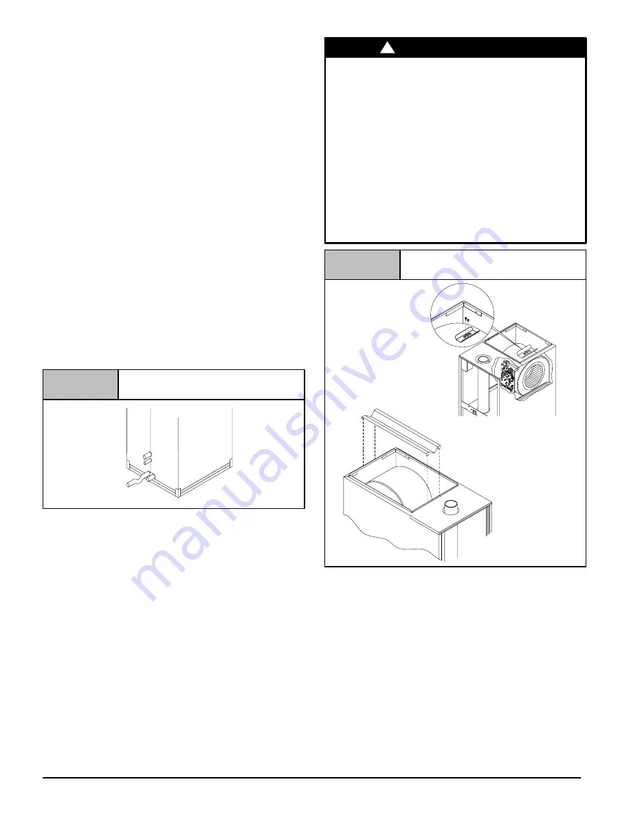
Condensate Line Raised by Base
Figure 16
Non-Combustible Floor:
Set the furnace over the opening in the floor. If necessary, grout
around the base to seal air leaks between the base and the floor.
Filters:
A filter MUST be used.
The 18
1
/
4
″
X 15
3
/
4
″
(463.5 x 400.1mm) framed high
−
velocity filters
supplied with the furnace may be installed in the return air plenum
above the furnace. A filter rack is supplied with each furnace. See
Figure 17.
Use either filter type:
•
Washable, high
−
velocity filters are based on a maximum air
flow rating of 600 FPM (3.0 m/s).
•
Disposable, low velocity filters are based on a maximum air
flow of 300 FPM (1.5 m/s) when used with external filter grille.
•
See
Circulation Air Blower Data
for additional information.
!
REDUCED FURNACE LIFE HAZARD
Failure to follow this caution may result in reduced
furnace life.
Use of excessively dirty and/or restrictive air filters
may increase furnace operating
temperatures and shorten the life of the furnace.
Filters supplied with the furnace are rated at a
maximum of 600 FPM (3.0 m/s) air velocity and sized
for the furnace’s airflow rate. Replacement filters
must be of equivalent type, size, and rating except as
described below.
Disposable, low
−
velocity filters may be used to
replace washable, high
−
velocity filters, providing
they are sized for 300 FPM (1.5 m/s) or less.
CAUTION
Figure 17
Filter Rack Installation
25-25-14a
OR
Version “A”
factory
−
attached to the
top of the blower housing
Version “B”
factory
−
supplied
but field installed
NOTE
: The return air plenum
MUST
extend a sufficient height
above the furnace (dimension “A” in
Figure 18
) to provide for the
attachment of a return air duct or grille above the filters.
NOTE
: Plenum must be fitted as close to the return air flange of the
furnace as possible to eliminate any air bypassing the filters.
Filters can only be installed through the right hand side of the fur-
nace blower opening. Slide filter into furnace until it is in position to
be pushed up and over into place on the left hand side of furnace.
See
Figure 18
.
Slide remaining filter into furnace and up into place on right hand
side of furnace. See
Figure 18
.
If there is insufficient plenum height for this type of installation, fil-
ters may be installed in any accessible location in the return air
system. In such a case, the filters should be of equivalent size and
style as originally supplied with the furnace.


