background image

INSTALLATION INSTRUCTIONS

R

410A Split System Air Conditioner

2

421 01 5104 02

Specifications subject to change without notice.

SAFETY CONSIDERATIONS

Improper installation, adjustment, alteration, service,

maintenance, or use can cause explosion, fire, electrical

shock, or other conditions which may cause death, personal

injury, or property damage. Consult a qualified installer,

service agency, or your distributor or branch for information or

assistance. The qualified installer or agency must use

factory

authorized kits or accessories when modifying this

product. Refer to the individual instructions packaged with

the kits or accessories when installing.
Follow all safety codes. Wear safety glasses, protective

clothing, and work gloves. Use quenching cloth for brazing

operations. Have fire extinguisher available. Read these

instructions thoroughly and follow all warnings or cautions

included in literature and  attached to the unit. Consult local

building codes and current editions of the National Electrical

Code ( NEC ) NFPA 70.  In Canada, refer to current editions

of the Canadian electrical code CSA 22.1.
Recognize safety information. This is the safety

alert symbol

!

 !

 When you see this symbol on the unit and in instructions

or manuals, be alert to the potential for personal injury.

Understand these signal words; DANGER, WARNING, and

CAUTION. These words are used with the safety

alert

symbol. DANGER identifies the most serious hazards which

will 

result in severe personal injury or death. WARNING

signifies hazards which 

could 

result in personal injury or

death. CAUTION is used to identify unsafe practices which

would 

result in minor personal injury or product and property

damage. NOTE is used to highlight suggestions which 

will

result in enhanced installation, reliability, or operation.

INSTALLATION RECOMMENDATIONS

NOTE

: In some cases noise in the living area has been

traced to gas pulsations from improper installation of

equipment.

1. Locate unit away from windows, patios, decks, etc.

where unit operation sound may disturb customer.

2. Ensure that vapor and liquid tube diameters are

appropriate for unit capacity.

3. Run refrigerant tubes as directly as possible by

avoiding unnecessary turns and bends.

4. Leave some slack between structure and unit to

absorb vibration.

5. When passing refrigerant tubes through the wall, seal

opening with RTV or other pliable silicon

based caulk.

(See Fig. 1.)

6. Avoid direct tubing contact with water pipes, duct work,

floor joists, wall studs, floors, and walls.

7. Do not suspend refrigerant tubing from joists and studs

with a rigid wire or strap which comes in direct contact

with tubing.(See Fig. 1.)

8. Ensure that tubing insulation is pliable and completely

surrounds vapor tube.

9. When necessary, use hanger straps which are 1 in.

(25.4 mm) wide and conform to shape of tubing

insulation. (See Fig. 1.)

10. Isolate hanger straps from insulation by using metal

sleeves bent to conform to shape of insulation.
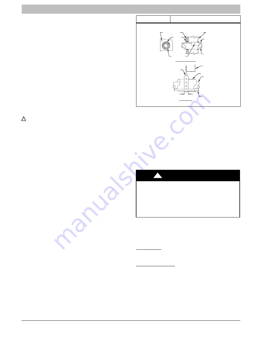
Figure 1

Connecting Tube Installation

INSULATION

VAPOR TUBE

LIQUID TUBE

OUTDOOR WALL

INDOOR WALL

LIQUID TUBE

VAPOR TUBE

INSULATION

CAULK

Avoid contact between tubing and structure

NOTE:

THROUGH THE WALL

HANGER STRAP

(AROUND VAPOR

TUBE ONLY)

JOIST

1

 (25.4 mm)MIN.

SUSPENSION

Outdoor unit contains system refrigerant charge for operation

with AHRI rated indoor unit when connected by 15 ft. (4.57

m) of field

supplied or factory accessory tubing. For proper

unit operation, check refrigerant charge using charging

information located on control box cover and/or in the Check

Charge section of this instruction.

IMPORTANT

: Maximum liquid

line size is 3/8

in. OD for all

residential applications including long line.

IMPORTANT

: Always install the factory

supplied liquid

line

filter drier. Obtain replacement filter driers from your
distributor or branch.

INSTALLATION

!

WARNING

UNIT OPERATION AND SAFETY HAZARD

Failure to follow this warning could result in personal

injury or equipment damage.
R

410A refrigerant systems operate at higher pressures

than standard R

22 systems.  Do not use R

22 service

equipment or components on R

410A refrigerant

equipment.

Specifications for this unit in residential new construction

market require the outdoor unit, indoor unit, refrigerant tubing

sets, metering device, and filter drier listed in presale

literature. There can be no deviation.

Check Equipment and Job Site

Unpack Unit

Move to final location. Remove carton taking care not to

damage unit.

Inspect Equipment

File claim with shipping company prior to installation if

shipment is damaged or incomplete. Locate unit rating plate

on unit corner panel. It contains information needed to

properly install unit. Check rating plate to be sure unit

matches job specifications.

Install on a Solid, Level Mounting Pad

If conditions or local codes require the unit be attached to

pad, tie down bolts should be used and fastened through

knockouts provided in unit base pan. Refer to unit mounting

pattern in Fig. 2 to determine base pan size and knockout

hole location.

Summary of Contents for CSA6

Page 1: ...ility or operation Signal Words in Manuals The signal word WARNING is used throughout this manual in the following manner The signal word CAUTION is used throughout this manual in the following manner Signal Words on Product Labeling Signal words are used in combination with colors and or pictures on product labels WARNING Safety Labeling and Signal Words CAUTION WARNING TABLE OF CONTENTS Safety C...

Page 2: ...ee Fig 1 6 Avoid direct tubing contact with water pipes duct work floor joists wall studs floors and walls 7 Do not suspend refrigerant tubing from joists and studs with a rigid wire or strap which comes in direct contact with tubing See Fig 1 8 Ensure that tubing insulation is pliable and completely surrounds vapor tube 9 When necessary use hanger straps which are 1 in 25 4 mm wide and conform to...

Page 3: ...operating ambient in cooling mode is 125 F 51 67_C Make Piping Connections WARNING PERSONAL INJURY AND ENVIRONMENTAL HAZARD Failure to follow this warning could result in personal injury or death Relieve pressure and recover all refrigerant before system repair or final unit disposal Use all service ports and open all flow control devices including solenoid valves CAUTION UNIT DAMAGE HAZARD Failur...

Page 4: ...ng line sets between 80 and 200 ft 24 38 and 60 96 m and or 20 ft 6 09 m vertical differential refer to Long Line Applications Guideline Table 2 Refrigerant Connections and Recommended Liquid and Vapor Tube Diameters In UNIT SIZE LIQUID RATED VAPOR up to 80 ft 24 38 m Connection and Tube Diameter Connection Diameter Rated Tube Diameter 18 24 30 3 8 3 4 3 4 36 42 48 3 8 7 8 7 8 60 3 8 7 8 1 1 8 Uni...

Page 5: ...using the recommended deep vacuum method of 500 microns An alternate triple evacuation method may be used See triple evacuation method in Service Manual IMPORTANT Always break a vacuum with dry nitrogen Deep Vacuum Method The deep vacuum method requires a vacuum pump capable of pulling a vacuum of 500 microns and a vacuum gage capable of accurately measuring this vacuum depth The deep vacuum metho...

Page 6: ...ired Final Wiring Check IMPORTANT Check factory wiring and field wire connections to ensure terminations are secured properly Check wire routing to ensure wires are not in contact with tubing sheet metal etc Compressor Crankcase Heater When equipped with a crankcase heater furnish power to heater a minimum of 24 hr before starting unit To furnish power to heater only set thermostat to OFF and clos...

Page 7: ...ommunicating mode make sure that indoor airflow is set to efficiency during charging If conditions are favorable check system charge by subcooling method If any adjustment is necessary adjust charge slowly and allow system to operate for 15 minutes to stabilize before declaring a properly charged system If the indoor temperature is above 80_F 26 67_C and the outdoor temperature is in the favorable...

Page 8: ... will be turned OFF until the next valid communication Amber Status Light An amber colored STATUS light is used to display the operation mode and fault codes as specified in the troubleshooting section See Table 3 for codes and definitions NOTE Only one fault code will be displayed on the outdoor unit control board the most recent with the highest priority Crankcase Heater Operation The crankcase ...

Page 9: ...RUCTIONS R 410A Split System Air Conditioner 421 01 5104 02 9 Specifications subject to change without notice terminals For operation in non communicating mode wire solenoid valve kit NASA401LS across C and Y terminals ...

Page 10: ... outdoor fan is turned off If the call for cooling continues the control will energize the compressor contactor every 15 minutes If the thermal protector closes at the next 15 minute interval check the unit will resume operation If the thermal cutout trips for three consecutive cycles then unit operation is locked out for 4 hours and the appropriate fault code See Table 3 is displayed CONTACTOR SH...

Page 11: ...il Sensor Fault 55 Coil sensor not reading or out of range Ohm out sensor and check wiring Thermistors out of range 56 Improper relationship between coil sensor and outdoor air sensor Ohm out sensors and check wiring Thermal Cutout 72 Compressor voltage sensed after start up then absent for 10 consecutive seconds while cooling demand exists Possible causes are internal compressor overload trip or ...

Page 12: ...INSTALLATION INSTRUCTIONS R 410A Split System Air Conditioner 12 421 01 5104 02 Specifications subject to change without notice Figure 9 Single Stage Control Board ...

Page 13: ...ite Red R Wall Control Variable Speed Furnace Fan Coil Outdoor Green Yellow White Red LEGEND 24V FACTORY WIRING 24V FIELD WIRING FIELD SPLICE CONNECTION C DX DX R Figure 11 Non Communicating Standard Thermostat 3 Wire 24V Circuit Connections See Thermostat Installation Instructions for Specific Unit combinations LEGEND 24 V FACTORY WIRING 24 V FIELD WIRING FIELD SPLICE CONNECTION ELECTRICAL OPERAT...

Page 14: ...OM HEAT STAGE 1 HEAT STAGE 2 INDOOR FAN LEGEND 24V FACTORY WIRING 24V FIELD WIRING FIELD SPLICE CONNECTION NOTE Wiring must conform to NEC or local codes Figure 13 Non Communicating Indoor with Observer Communicating Wall Control NAXA00101DB Green Yellow White Red OAT Sensor Communicating Outdoor W2 C Y R C R Wall Control OAT DX R C DX Y G O C Y Y2 R W2 G DX R C DX Non Communicating Indoor NOTE Th...

Page 15: ...as with other HFC refrigerants is only compatible with POE oils Vacuum pumps will not remove moisture from oil Do not use liquid line filter driers with rated working pressures less than 600 psig Do not install a suction line filter drier in liquid line POE oils absorb moisture rapidly Do not expose oil to atmosphere POE oils may cause damage to certain plastics and roofing materials Wrap all filt...

Reviews: