background image

INSTALLATION INSTRUCTIONS

R

410A Split System Air Conditioner

421 01 5104 02

3

Specifications subject to change without notice.

For hurricane tie downs 

 contact  your local distributor for

details and PE (Professional Certification), if required by local

authorities.
On rooftop applications, mount on level platform or frame.

Place unit above a load

bearing wall and isolate unit and

tubing set from structure. Arrange supporting members to

adequately support unit and minimize transmission of

vibration to building. Consult local codes governing rooftop

applications.
Roof mounted units exposed to winds may require wind

baffles. Consult the Low

Ambient pressure switch installation

instructions for wind baffle construction.

NOTE

: Unit must be level to within 

±

2

_

  (

±

3/8 in./ft..) per

compressor manufacturer specifications.

Clearance Requirements

When installing, allow sufficient space for airflow clearance,

wiring, refrigerant piping, and service. Allow 30 in. (762 mm)

clearance to service end of unit and 48 in. (1219.2 mm)

above unit. For proper airflow, a 6 in. (152.4 mm)  clearance

on one side of unit and 12 in. (304.8 mm) on all remaining

sides must be maintained. Maintain a distance of 24 in.

(609.6 mm) between units. Position so water, snow, or ice

from roof or eaves cannot fall directly on unit.
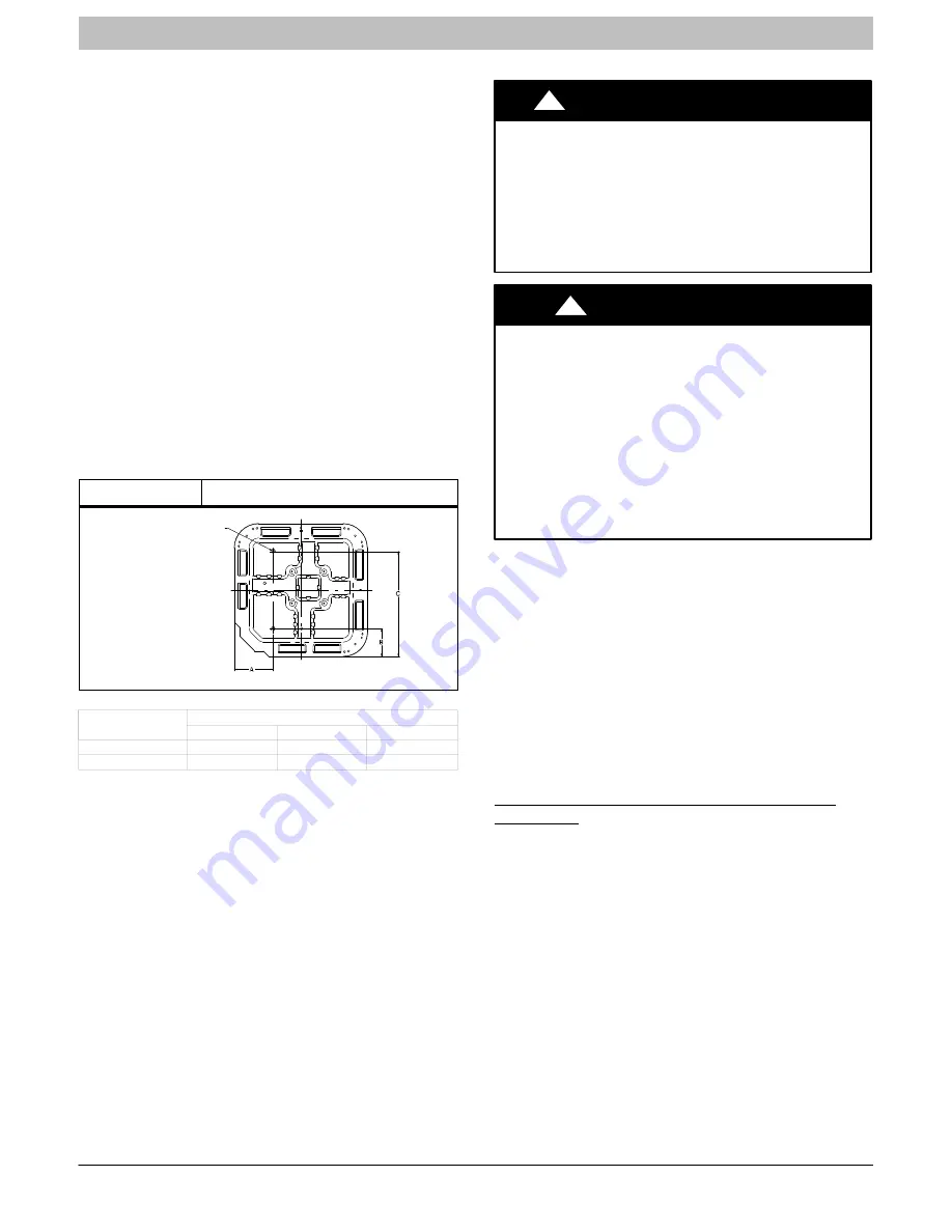
Figure 2

Tie Down Knockouts

3/8-in. (9.53 mm) Dia.
Tiedown Knockouts in
Basepan(2) Places

View From Top

UNIT BASE PAN

Dimension

TIEDOWN KNOCKOUT LOCATIONS in. (mm)

A

B

C

31–1/2 X 31–1/2

9–1/8 (231.8)

6–9/16 (166.7)

24–11/16 (627.1)

35 X 35

9–1/8 (231.8)

6–9/16 (166.7)

28–7/16 (722.3)

On rooftop applications, locate unit at least 6 in. (152.4 mm)

above roof surface.

Operating Ambient

The minimum outdoor operating ambient  in cooling mode is

55

°

F (12.78

_

C) without low ambient cooling enabled, and the

maximum outdoor operating ambient in cooling mode is

125

°

F (51.67

_

C).

Make Piping Connections

!

WARNING

PERSONAL INJURY AND ENVIRONMENTAL

HAZARD

Failure to follow this warning could result in personal

injury or death.
Relieve pressure and recover all refrigerant before system

repair or final unit disposal.
Use all service ports and open all flow

control devices,

including solenoid valves.

CAUTION

!

UNIT DAMAGE HAZARD

Failure to follow this caution may result in equipment

damage or improper operation.
Do not leave system open to atmosphere any longer than

minimum required for installation. POE oil in compressor is

extremely susceptible to moisture absorption. Always keep

ends of tubing sealed during installation.
If ANY refrigerant tubing is buried, provide a 6 in. (152.4

mm) vertical rise at service valve.  Refrigerant tubing

lengths up to 36 in. (914.4 mm) may be buried without

further special consideration.  Do not bury lines more than

36 in. (914.4 mm).

Outdoor units may be connected to indoor section using

accessory tubing package or field

supplied refrigerant grade

tubing of correct size and condition. For tubing requirements

beyond 80 ft/24.38 m, substantial capacity and performance

losses can occur. Following the recommendations in the

Long Line Applications Guideline for Split

System Air

Conditioners and Heat Pumps will reduce these losses. Refer

to Table 1 for accessory requirements. Refer to Table 2 for

field tubing diameters.
There are no buried

line applications greater than 36 in.

(914.4 mm).
If refrigerant tubes or indoor coil are exposed to atmosphere,

they must be evacuated to 500 microns to eliminate

contamination and moisture in the system.

Outdoor Unit Connected to Factory Approved

Indoor Unit

Outdoor unit contains correct system refrigerant charge for

operation with factory approved AHRI rated indoor unit  when

c o n n e c t e d  b y 1 5  f t . ( 4 . 5 7  m ) o f f i e l d

s u p p l i e d  o r

factory

accessory tubing, and factory supplied filter drier.

Check refrigerant charge for maximum efficiency.

Summary of Contents for CSA6

Page 1: ...ility or operation Signal Words in Manuals The signal word WARNING is used throughout this manual in the following manner The signal word CAUTION is used throughout this manual in the following manner Signal Words on Product Labeling Signal words are used in combination with colors and or pictures on product labels WARNING Safety Labeling and Signal Words CAUTION WARNING TABLE OF CONTENTS Safety C...

Page 2: ...ee Fig 1 6 Avoid direct tubing contact with water pipes duct work floor joists wall studs floors and walls 7 Do not suspend refrigerant tubing from joists and studs with a rigid wire or strap which comes in direct contact with tubing See Fig 1 8 Ensure that tubing insulation is pliable and completely surrounds vapor tube 9 When necessary use hanger straps which are 1 in 25 4 mm wide and conform to...

Page 3: ...operating ambient in cooling mode is 125 F 51 67_C Make Piping Connections WARNING PERSONAL INJURY AND ENVIRONMENTAL HAZARD Failure to follow this warning could result in personal injury or death Relieve pressure and recover all refrigerant before system repair or final unit disposal Use all service ports and open all flow control devices including solenoid valves CAUTION UNIT DAMAGE HAZARD Failur...

Page 4: ...ng line sets between 80 and 200 ft 24 38 and 60 96 m and or 20 ft 6 09 m vertical differential refer to Long Line Applications Guideline Table 2 Refrigerant Connections and Recommended Liquid and Vapor Tube Diameters In UNIT SIZE LIQUID RATED VAPOR up to 80 ft 24 38 m Connection and Tube Diameter Connection Diameter Rated Tube Diameter 18 24 30 3 8 3 4 3 4 36 42 48 3 8 7 8 7 8 60 3 8 7 8 1 1 8 Uni...

Page 5: ...using the recommended deep vacuum method of 500 microns An alternate triple evacuation method may be used See triple evacuation method in Service Manual IMPORTANT Always break a vacuum with dry nitrogen Deep Vacuum Method The deep vacuum method requires a vacuum pump capable of pulling a vacuum of 500 microns and a vacuum gage capable of accurately measuring this vacuum depth The deep vacuum metho...

Page 6: ...ired Final Wiring Check IMPORTANT Check factory wiring and field wire connections to ensure terminations are secured properly Check wire routing to ensure wires are not in contact with tubing sheet metal etc Compressor Crankcase Heater When equipped with a crankcase heater furnish power to heater a minimum of 24 hr before starting unit To furnish power to heater only set thermostat to OFF and clos...

Page 7: ...ommunicating mode make sure that indoor airflow is set to efficiency during charging If conditions are favorable check system charge by subcooling method If any adjustment is necessary adjust charge slowly and allow system to operate for 15 minutes to stabilize before declaring a properly charged system If the indoor temperature is above 80_F 26 67_C and the outdoor temperature is in the favorable...

Page 8: ... will be turned OFF until the next valid communication Amber Status Light An amber colored STATUS light is used to display the operation mode and fault codes as specified in the troubleshooting section See Table 3 for codes and definitions NOTE Only one fault code will be displayed on the outdoor unit control board the most recent with the highest priority Crankcase Heater Operation The crankcase ...

Page 9: ...RUCTIONS R 410A Split System Air Conditioner 421 01 5104 02 9 Specifications subject to change without notice terminals For operation in non communicating mode wire solenoid valve kit NASA401LS across C and Y terminals ...

Page 10: ... outdoor fan is turned off If the call for cooling continues the control will energize the compressor contactor every 15 minutes If the thermal protector closes at the next 15 minute interval check the unit will resume operation If the thermal cutout trips for three consecutive cycles then unit operation is locked out for 4 hours and the appropriate fault code See Table 3 is displayed CONTACTOR SH...

Page 11: ...il Sensor Fault 55 Coil sensor not reading or out of range Ohm out sensor and check wiring Thermistors out of range 56 Improper relationship between coil sensor and outdoor air sensor Ohm out sensors and check wiring Thermal Cutout 72 Compressor voltage sensed after start up then absent for 10 consecutive seconds while cooling demand exists Possible causes are internal compressor overload trip or ...

Page 12: ...INSTALLATION INSTRUCTIONS R 410A Split System Air Conditioner 12 421 01 5104 02 Specifications subject to change without notice Figure 9 Single Stage Control Board ...

Page 13: ...ite Red R Wall Control Variable Speed Furnace Fan Coil Outdoor Green Yellow White Red LEGEND 24V FACTORY WIRING 24V FIELD WIRING FIELD SPLICE CONNECTION C DX DX R Figure 11 Non Communicating Standard Thermostat 3 Wire 24V Circuit Connections See Thermostat Installation Instructions for Specific Unit combinations LEGEND 24 V FACTORY WIRING 24 V FIELD WIRING FIELD SPLICE CONNECTION ELECTRICAL OPERAT...

Page 14: ...OM HEAT STAGE 1 HEAT STAGE 2 INDOOR FAN LEGEND 24V FACTORY WIRING 24V FIELD WIRING FIELD SPLICE CONNECTION NOTE Wiring must conform to NEC or local codes Figure 13 Non Communicating Indoor with Observer Communicating Wall Control NAXA00101DB Green Yellow White Red OAT Sensor Communicating Outdoor W2 C Y R C R Wall Control OAT DX R C DX Y G O C Y Y2 R W2 G DX R C DX Non Communicating Indoor NOTE Th...

Page 15: ...as with other HFC refrigerants is only compatible with POE oils Vacuum pumps will not remove moisture from oil Do not use liquid line filter driers with rated working pressures less than 600 psig Do not install a suction line filter drier in liquid line POE oils absorb moisture rapidly Do not expose oil to atmosphere POE oils may cause damage to certain plastics and roofing materials Wrap all filt...

Reviews: