background image

INSTALLATION INSTRUCTIONS

R

410A Split System Air Conditioner

6

421 01 5104 02

Specifications subject to change without notice.

!

WARNING

ELECTRICAL SHOCK HAZARD

Failure to follow this warning could result in personal

injury or death.
The unit cabinet must have an uninterrupted or

unbroken ground to minimize personal injury if an

electrical fault should occur. The ground may consist

of electrical wire or metal conduit when installed in

accordance with existing electrical codes.

Connect Ground and Power Wires

Connect ground wire to ground connection in control box for

safety. Connect power wiring to contactor as shown in Fig. 5.

Figure 5

Line Power Connections

DISCONNECT

PER N. E. C. AND/OR

LOCAL CODES

CONTACTOR

GROUND

LUG

FIELD GROUND

WIRING

FIELD POWER

WIRING

Connect Control Wiring

Route 24

v control wires through control wiring grommet and

connect leads to control wiring. (See Fig. 10 & Fig. 11)
Use No. 18 AWG color

coded, insulated (35

_

C minimum)

wire. If  thermostat is located more than 100 ft. (30.48 m)

from unit, as measured along the control voltage wires, use

No. 16 AWG color

coded, insulated wire to avoid excessive

voltage drop.
All wiring must be NEC Class 1 and must be separated from

incoming power leads.
Use furnace transformer, fan coil transformer, or accessory

transformer for control power, 24

v/40

va minimum.

NOTE

: Use of available 24

v accessories may exceed the

minimum 40

va power requirement. Determine total

transformer load and increase the transformer capacity or
split the load with an accessory transformer as required.

Final Wiring Check

IMPORTANT

:  Check factory wiring and field wire

connections  to ensure terminations are secured properly.

Check wire routing to ensure wires are not in contact with
tubing, sheet metal, etc.

Compressor Crankcase Heater

When equipped with a crankcase heater, furnish power to

heater a minimum of 24 hr before starting unit. To furnish

power to heater only, set thermostat to OFF and close

electrical disconnect to outdoor unit.

A crankcase heater is required for low

ambient cooling or if

refrigerant tubing is longer than 80 ft. (24.38 m).  Refer to the

Long Line Applications Guideline 

 Residential Split

System

Air Conditioners and Heat Pumps Using R

410A Refrigerant.

Install Electrical Accessories

Refer to the individual instructions packaged with kits or

accessories when installing.

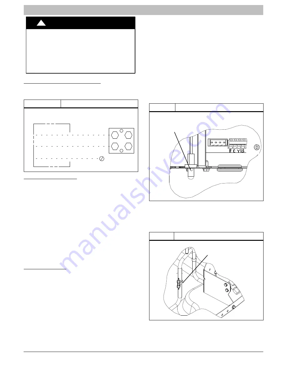
Check OAT Thermistor and OCT Thermistor

Attachments

Outdoor Air Temperature (OAT) Thermistor is factory installed

by inserting the nibs on either sides of the thermistor body

through a keyhole in the bottom shelf of the control box and

locking it in place by turning it 90 degrees, such that the

spherical end of a nib faces the front of the control box.
Check to make sure the OAT is locked in place.  See Fig. 6.

Figure 6

Outdoor Air Thermistor (OAT) Attachment

OAT Thermistor must be locked in place

with spherical nib end facing towards

the front of the control box

DX+ DX- C R

The Outdoor Coil Temperature (OCT) Thermistor is factory

installed on the liquid tube between the coil assembly and the

liquid service valve.  See Fig. 7.
Check to make sure the thermistor is securely attached on

the liquid tube with the clip as shown in Fig. 7.

Figure 7

Outdoor Coil Thermistor (OAT) Attachment

OCT Thermistor must be 

secured tight on the liquid tube.

Summary of Contents for CSA6

Page 1: ...ility or operation Signal Words in Manuals The signal word WARNING is used throughout this manual in the following manner The signal word CAUTION is used throughout this manual in the following manner Signal Words on Product Labeling Signal words are used in combination with colors and or pictures on product labels WARNING Safety Labeling and Signal Words CAUTION WARNING TABLE OF CONTENTS Safety C...

Page 2: ...ee Fig 1 6 Avoid direct tubing contact with water pipes duct work floor joists wall studs floors and walls 7 Do not suspend refrigerant tubing from joists and studs with a rigid wire or strap which comes in direct contact with tubing See Fig 1 8 Ensure that tubing insulation is pliable and completely surrounds vapor tube 9 When necessary use hanger straps which are 1 in 25 4 mm wide and conform to...

Page 3: ...operating ambient in cooling mode is 125 F 51 67_C Make Piping Connections WARNING PERSONAL INJURY AND ENVIRONMENTAL HAZARD Failure to follow this warning could result in personal injury or death Relieve pressure and recover all refrigerant before system repair or final unit disposal Use all service ports and open all flow control devices including solenoid valves CAUTION UNIT DAMAGE HAZARD Failur...

Page 4: ...ng line sets between 80 and 200 ft 24 38 and 60 96 m and or 20 ft 6 09 m vertical differential refer to Long Line Applications Guideline Table 2 Refrigerant Connections and Recommended Liquid and Vapor Tube Diameters In UNIT SIZE LIQUID RATED VAPOR up to 80 ft 24 38 m Connection and Tube Diameter Connection Diameter Rated Tube Diameter 18 24 30 3 8 3 4 3 4 36 42 48 3 8 7 8 7 8 60 3 8 7 8 1 1 8 Uni...

Page 5: ...using the recommended deep vacuum method of 500 microns An alternate triple evacuation method may be used See triple evacuation method in Service Manual IMPORTANT Always break a vacuum with dry nitrogen Deep Vacuum Method The deep vacuum method requires a vacuum pump capable of pulling a vacuum of 500 microns and a vacuum gage capable of accurately measuring this vacuum depth The deep vacuum metho...

Page 6: ...ired Final Wiring Check IMPORTANT Check factory wiring and field wire connections to ensure terminations are secured properly Check wire routing to ensure wires are not in contact with tubing sheet metal etc Compressor Crankcase Heater When equipped with a crankcase heater furnish power to heater a minimum of 24 hr before starting unit To furnish power to heater only set thermostat to OFF and clos...

Page 7: ...ommunicating mode make sure that indoor airflow is set to efficiency during charging If conditions are favorable check system charge by subcooling method If any adjustment is necessary adjust charge slowly and allow system to operate for 15 minutes to stabilize before declaring a properly charged system If the indoor temperature is above 80_F 26 67_C and the outdoor temperature is in the favorable...

Page 8: ... will be turned OFF until the next valid communication Amber Status Light An amber colored STATUS light is used to display the operation mode and fault codes as specified in the troubleshooting section See Table 3 for codes and definitions NOTE Only one fault code will be displayed on the outdoor unit control board the most recent with the highest priority Crankcase Heater Operation The crankcase ...

Page 9: ...RUCTIONS R 410A Split System Air Conditioner 421 01 5104 02 9 Specifications subject to change without notice terminals For operation in non communicating mode wire solenoid valve kit NASA401LS across C and Y terminals ...

Page 10: ... outdoor fan is turned off If the call for cooling continues the control will energize the compressor contactor every 15 minutes If the thermal protector closes at the next 15 minute interval check the unit will resume operation If the thermal cutout trips for three consecutive cycles then unit operation is locked out for 4 hours and the appropriate fault code See Table 3 is displayed CONTACTOR SH...

Page 11: ...il Sensor Fault 55 Coil sensor not reading or out of range Ohm out sensor and check wiring Thermistors out of range 56 Improper relationship between coil sensor and outdoor air sensor Ohm out sensors and check wiring Thermal Cutout 72 Compressor voltage sensed after start up then absent for 10 consecutive seconds while cooling demand exists Possible causes are internal compressor overload trip or ...

Page 12: ...INSTALLATION INSTRUCTIONS R 410A Split System Air Conditioner 12 421 01 5104 02 Specifications subject to change without notice Figure 9 Single Stage Control Board ...

Page 13: ...ite Red R Wall Control Variable Speed Furnace Fan Coil Outdoor Green Yellow White Red LEGEND 24V FACTORY WIRING 24V FIELD WIRING FIELD SPLICE CONNECTION C DX DX R Figure 11 Non Communicating Standard Thermostat 3 Wire 24V Circuit Connections See Thermostat Installation Instructions for Specific Unit combinations LEGEND 24 V FACTORY WIRING 24 V FIELD WIRING FIELD SPLICE CONNECTION ELECTRICAL OPERAT...

Page 14: ...OM HEAT STAGE 1 HEAT STAGE 2 INDOOR FAN LEGEND 24V FACTORY WIRING 24V FIELD WIRING FIELD SPLICE CONNECTION NOTE Wiring must conform to NEC or local codes Figure 13 Non Communicating Indoor with Observer Communicating Wall Control NAXA00101DB Green Yellow White Red OAT Sensor Communicating Outdoor W2 C Y R C R Wall Control OAT DX R C DX Y G O C Y Y2 R W2 G DX R C DX Non Communicating Indoor NOTE Th...

Page 15: ...as with other HFC refrigerants is only compatible with POE oils Vacuum pumps will not remove moisture from oil Do not use liquid line filter driers with rated working pressures less than 600 psig Do not install a suction line filter drier in liquid line POE oils absorb moisture rapidly Do not expose oil to atmosphere POE oils may cause damage to certain plastics and roofing materials Wrap all filt...

Reviews: