background image

SERVICE AND TECHNICAL SUPPORT MANUAL

Gas Furnace: F9MES

Specifications  subject to change without notice.

6

440 04 4900 02

3. Connect a manometer to the inlet pressure tap on gas

valve.

4. Turn on furnace power supply.
5. Turn gas supply manual shutoff valve to ON position.
6. Turn furnace gas valve switch to ON position.
7. Jumper R and W thermostat connections at the furnace

control board.

8. When main burners ignite, confirm inlet gas pressure is

between 4.5 in. w.c. (1125 Pa) and 13.6 in. w.c. (3388

Pa).

9. Remove jumper across thermostat connections to

terminate call for heat. Wait until the blower off delay is

completed.

10. Turn furnace gas valve electric switch to OFF position.

11. Turn gas supply manual shutoff valve to OFF position.

12. Turn off furnace power supply.
13. Remove manometer from the inlet pressure tap of the

gas valve.

FIRE HAZARD

Failure to follow this warning could result in personal injury,

death, and/or property damage.

Re

install manifold pressure tap plug in gas valve to

prevent gas leak.

!

WARNING

14. Apply pipe dope sparingly to end of inlet gas pipe plug

and re

install in the gas valve.

Adjust Manifold Pressure

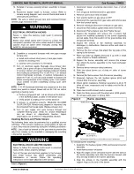
1. Adjust manifold pressure to obtain proper gas input rate.

(See 

Figure 3

)

a. Turn gas valve ON/OFF switch to OFF.
b. Remove manifold pressure tap plug from gas valve.

c. Connect a water column manometer or similar device

to manifold pressure tap.

d. Turn gas valve ON/OFF switch to ON.
e. Manually close blower door switch.

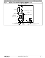
f. Jumper R and W thermostat connections on control

to start furnace. (See 

Figure 4

)

g. Remove regulator adjustment cap from gas valve

pressure regulator (See 

Figure 3

) and turn adjusting

screw (3/16 or smaller flat

tipped screwdriver)

counterclockwise (out) to decrease input rate or

clockwise (in) to increase input rate.

NOTICE

DO NOT set manifold pressure less than 2.8

in. w.c. (697 Pa)

or more than 3.8

in. w.c. (947 Pa) for natural gas. If required

manifold pressure is outside this range, change main burner

orifices.

h. When correct input is obtained, replace cap that

conceal gas valve regulator adjustment screw.  Main

burner flame should be clear blue, almost transparent

(See 

Figure 13

)

i. Remove jumper R to W.

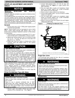
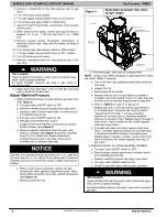
Figure 3

Redundant Automatic Gas Valve

(Single Stage)

ON/OFF Switch

Regulator Seal Cap

Regulator Adjustment

Regulator Seal Cap under Cap

1/2” NPT Outlet

1/8” NPT Manifold

Pressure Tap

1/8” NPT Inlet

Pressure Tap

1/2” NPT Inlet

A11153

2. Verify natural gas  input rate by clocking meter.

NOTE

:  Contact your HVAC distributor or gas supplier for metric

gas meter Tables, if required.

a. Turn off all other gas appliances and pilots served by

the meter.

b. Jumper R to W.

c. Run furnace for 3 minutes.

d. Measure time (in sec) for gas meter to complete 1

revolution and note reading. The 2 or 5 cubic feet dial

provides a more accurate measurement of gas flow.

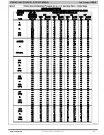
e. Refer to 

Table 2

 for cubic ft. of gas per hr.

f. Multiply gas rate cu ft./hr by heating value (Btuh/cu

ft.) to obtain input. If clocked rate does not match

required input from Step 1, increase manifold

pressure to increase input or decrease manifold

pressure to decrease input. Repeat steps b through e

until correct   input is achieved. Re

install regulator

seal cap on gas valve.

g. If clocked rate does not match required input from

Step 1, increase manifold pressure to increase input

or decrease manifold pressure to decrease input.

Repeat steps b through e of Step 1 until correct heat

input is achieved. Re--install regulator seal cap on

gas valve.

3.

Restore furnace to normal operating condition.

a. Turn gas valve ON/OFF switch to OFF.
b. Remove water column manometer or similar device

from manifold pressure tap.

c. Replace manifold pressure tap plug to gas valve.

d. Turn gas valve ON/OFF switch to ON.
e. Check for gas leaks and verify furnace operation

FIRE HAZARD

Failure to follow this warning could result in personal injury,

death, and/or property damage.
Reinstall manifold pressure tap plug in gas valve to prevent

gas leak.

!

WARNING

Summary of Contents for F9MES Series

Page 1: ...this manual in the following manner CAUTION Signal Words on Product Labeling Signal words are used in combination with colors and or pictures or product labels The signal word WARNING is used through...

Page 2: ...d result in personal injury or death CAUTION is used to identify unsafe practices which may result in minor personal injury or product and property damage NOTE is used to highlight suggestions which w...

Page 3: ...d ON Type of Gas Natural Propane Filter Type and Size Check in box the Blower OFF Delay Jumper Heating Position for Fan Time OFF Setting 1 and 2 2 and 3 Position Time Off Position Time Off 90 108 120...

Page 4: ...ates HUM 220vac terminal is only energized when the draft inducer is energized in heating HUM 24vac terminal is only energized on a call for heat W and the LPS is closed Prime Condensate Trap with Wat...

Page 5: ...ific gravity of the gas To do this 1 Obtain average yearly gas heat value at installed altitude from local gas supplier 2 Obtain average yearly gas specific gravity from local gas supplier 3 Find inst...

Page 6: ...r natural gas If required manifold pressure is outside this range change main burner orifices h When correct input is obtained replace cap that conceal gas valve regulator adjustment screw Main burner...

Page 7: ...24 VAC CONNECTIONS P2 HOT SURFACE IGNITOR HSI INDUCER MOTOR IND CONNECTOR 220 VAC L1 LINE VOLTAGE CONNECTION SPARE1 COM BLUE 220 VAC L2 NEUTRAL CONNECTIONS 24 V THERMOSTAT TERMINALS HUMIDIFIER TERMINA...

Page 8: ...300 21 171 343 857 62 58 116 290 22 164 327 818 64 56 112 281 23 157 313 783 66 54 109 273 24 150 300 750 68 53 106 265 25 144 288 720 70 51 103 257 26 138 277 692 72 50 100 250 27 133 267 667 74 48 9...

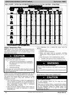
Page 9: ...CE AND TECHNICAL SUPPORT MANUAL Gas Furnace F9MES Specifications subject to change without notice 440 04 4900 02 9 Table 3 Orifice Size and Manifold Pressure in w c for Gas Input Rate Single Stage L12...

Page 10: ...ometers in return and supply ducts as close to furnace as possible Be sure thermometers do not see heat exchangers so that radiant heat does not affect thermometer readings This is particularly import...

Page 11: ...sub base terminals or R and W wires at wall 3 Record amp draw across terminals when furnace is in low heat and after blower starts 4 Set heat anticipator on thermostat per thermostat instructions and...

Page 12: ...1955 1905 1850 1795 1740 1685 1630 1575 Yellow 4 0 1755 1710 1660 1610 1565 1515 1465 1415 1365 1310 Orange 5 3 5 1590 1540 1495 1450 1400 1355 1310 1260 1205 1145 Red 5 3 5 1450 1400 1355 1310 1265...

Page 13: ...t location accordingly Figure 6 Multipoise Orientations A93041 Electrical Controls and Wiring Pressure Switches Each pressure switch is labeled with the reference location noted as COLLECTOR BOX LPS o...

Page 14: ...interpret the LED 6 A component test sequence will follow 7 Reinstall the Main Control door Component Self Test NOTE The furnace control component test allows all components to run for a short time ex...

Page 15: ...connections for tightness and controls for proper operation each heating season Service as necessary 4 Inspect burner compartment before each heating season for rust corrosion soot or excessive dust I...

Page 16: ...t on blower wheel remove wheel from the blower housing and wash it with an appropriate degreaser To remove wheel a Mark blower wheel location on shaft before disassembly to ensure proper reassembly b...

Page 17: ...ld or damaging the mounting to the burner assembly ELECTRICAL SHOCK AND FIRE HAZARD Failure to follow this warning could result in personal injury death and or property damage Turn off the gas and ele...

Page 18: ...ontrol door when complete Servicing Hot Surface Igniter The igniter does NOT require annual inspection Check igniter resistance before removal Refer to Figure 9 Figure 10 and Figure 11 1 Turn off gas...

Page 19: ...to the condensate trap 7 Connect the leads of the condensate heat pad if used 8 Connect external drain piping to the condensate drain elbow or drain extension pipe 9 Turn gas on at electric switch on...

Page 20: ...C or lower freeze protection measures must be taken to prevent property or product damage CAUTION Since the furnace uses a condensing heat exchanger some water will accumulate in the unit as a result...

Page 21: ...SERVICE AND TECHNICAL SUPPORT MANUAL Gas Furnace F9MES Specifications subject to change without notice 440 04 4900 02 21 Figure 14 Service Label 339462 2 Rev A...

Page 22: ...SERVICE AND TECHNICAL SUPPORT MANUAL Gas Furnace F9MES Specifications subject to change without notice 22 440 04 4900 02 339542 2 Rev A...

Page 23: ...SERVICE AND TECHNICAL SUPPORT MANUAL Gas Furnace F9MES Specifications subject to change without notice 440 04 4900 02 23 Figure 15 Wiring Diagram 339462 2 Rev A...

Page 24: ...SERVICE AND TECHNICAL SUPPORT MANUAL Gas Furnace F9MES Specifications subject to change without notice 24 440 04 4900 02 339542 2 Rev A...

Page 25: ...equence Gas valve and humidifier will not be turned on Inducer motor will start and remain on until the end of the blower test then off The following components are on for 10 15 seconds each individua...

Page 26: ...onent test Does the igniter glow orange white by the end of the 18 second warm up period Unplug igniter harness from control and repeat component test Check for 220V between connector P2 HSI and NEUTR...

Page 27: ...the gas valve GV is energized Simultaneously the electronic air cleaner terminal EAC is energized and remains energized as long as the blower motor BLWM is energized f Heat Off Delay When the thermos...

Page 28: ...injury death or property damage Improper installation adjustment alteration service maintenance or use can cause carbon monoxide poisoning explosion fire electrical shock or other conditions which may...

Reviews: