


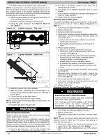
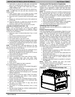
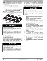


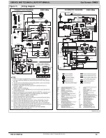
SERVICE AND TECHNICAL SUPPORT MANUAL
Gas Furnace: F9MES
Specifications subject to change without notice.
8
440 04 4900 02
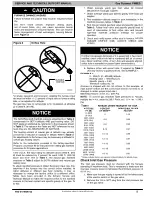
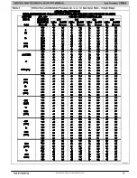
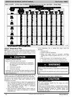
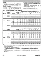
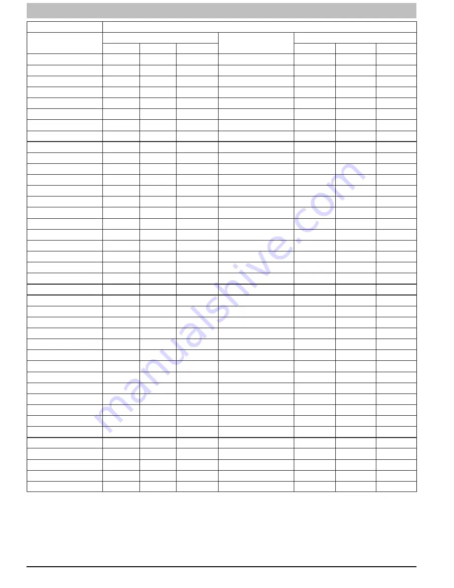
Table 2
Gas Rate (CU ft./hr)
SECONDS
FOR 1 REVOLUTION
SIZE OF TEST DIAL
SECONDS
FOR 1 REVOLUTION
SIZE OF TEST DIAL
1 Cu Ft.
2 Cu Ft.
5 Cu Ft.
1 Cu Ft.
2 Cu Ft.
5 Cu Ft.
10
360
720
1800
50
72
144
360
11
327
655
1636
51
71
141
355
12
300
600
1500
52
69
138
346
13
277
555
1385
53
68
136
340
14
257
514
1286
54
67
133
333
15
240
480
1200
55
65
131
327
16
225
450
1125
56
64
129
321
17
212
424
1059
57
63
126
316
18
200
400
1000
58
62
124
310
19
189
379
947
59
61
122
305
20
180
360
900
60
60
120
300
21
171
343
857
62
58
116
290
22
164
327
818
64
56
112
281
23
157
313
783
66
54
109
273
24
150
300
750
68
53
106
265
25
144
288
720
70
51
103
257
26
138
277
692
72
50
100
250
27
133
267
667
74
48
97
243
28
129
257
643
76
47
95
237
29
124
248
621
78
46
92
231
30
120
240
600
80
45
90
225
31
116
232
581
82
44
88
220
32
113
225
563
84
43
86
214
33
109
218
545
86
42
84
209
34
106
212
529
88
41
82
205
35
103
206
514
90
40
80
200
36
100
200
500
92
39
78
196
37
97
195
486
94
38
76
192
38
95
189
474
96
38
75
188
39
92
185
462
98
37
74
184
40
90
180
450
100
36
72
180
41
88
176
439
102
35
71
178
42
86
172
429
104
35
69
173
43
84
167
419
106
34
68
170
44
82
164
409
108
33
67
167
45
80
160
400
110
33
65
164
46
78
157
391
112
32
64
161
47
76
153
383
116
31
62
155
48
75
150
375
120
30
60
150
49
73
147
367


