background image

22

PARTS LIST

Model: MBO115DABR-D

B50040B

445 01 4054 06

Summary of Contents for FLO115DABR-C

Page 1: ...5DABR D OLF140C12C OLR182A16C D N S 0 5 9 4 R v A D N S 0 6 6 5 R v A D N S 0 5 7 5 R v A Manufactured by UTC Canada Corporation ICP Division 3400 Industrial Boulevard Sherbrooke Quebec Canada J1L 1V8...

Page 2: ...ician familiar with safety procedures and equipped with the proper tools and test instruments Failure to carefully read and follow all instructions in this manual can result in death and or personal i...

Page 3: ...mber Normal servicing of this unit does not require cleaning of the combustion chamber Use extreme care if for any reason you have to work in the area of the combustion chamber 1 2 2 Freezing temperat...

Page 4: ...r size and adequate chimney base temperature as specified in the Installation Code The relevant excerpt from the code is found in this section Use it as a guide when local or national codes do not exi...

Page 5: ...o provide adequate combustion and ventilation air can result in death and or personal injury 1 5 1 General Oil furnaces must have an adequate supply of combustion air It is common practice to assume t...

Page 6: ...vinyl vapour barrier CAUTION The CAS 2B does not turn the furnace installation into a direct vent system Therefore the building structure must provide for adequate combustion air to be delivered to t...

Page 7: ...heat exchanger warranty intact WARNING Fire and explosion hazard Use only approved heating type oil in this furnace DO NOT USE waste oil used motor oil gasoline or kerosene Use of these will result in...

Page 8: ...here the furnace is located Install the air conditioning cooling coil evaporator downstream from the supply air plenum of the furnace If a separate evaporator and blower unit is used install appropria...

Page 9: ...off the disconnect switch and CALL A QUALIFIED SERVICE TECHNICIAN CAUTION Do not attempt to start the burner when excess oil has accumulated when the furnace is full of vapour or when the combustion c...

Page 10: ...nd blower regulator Modification of the FAN ON and HI Limit settings on the Fan Limit and blower regulator can cause a malfunction of the furnace and carry to premature wear of the heat exchanger CAUT...

Page 11: ...inder with a stiff brush and vacuum cleaner 7 The heat exchanger and combustion chamber should be inspected to determine if replacement is required before re assembling the unit 8 After cleaning repla...

Page 12: ...ntion head 3 1 5 Nozzle Replace the nozzle with the one specified in Tables 3 1 to 3 4 p 15 to 18 3 1 6 Oil filter Tank filter The tank filter should be replaced as required Secondary filter The 10 mi...

Page 13: ...e Day Night Dealer name and address START UP TEST RESULTS Nozzle Pressure Lb psi Burner adjustments Primary air Fine air Draw Assembly CO2 Smoke scale Bacharach Gross stack temperature F Ambient tempe...

Page 14: ...5 1 2 75 2 3 75 AERO BURNER 1725 RPM Nozzle 100 PSIG pump pressure Delavan 0 65 70W 0 75 70W 0 85 70W Volts Hertz Phase Operating voltage range Rated voltage Amps Minimum ampacity for wiring sizing Ma...

Page 15: ...Nozzle Delavan 060 60W 075 60W 0 85 60W 0 85 60W Pump pressure PSIG 155 130 140 170 Combustion air adjustment turbulator damper 2 3 25 2 5 4 2 2 5 3 2 5 AERO BURNER 1725 RPM Nozzle 100 PSIG pump press...

Page 16: ...6 6 RIELLO BURNER MODEL 40 Nozzle Delavan 0 85 60W 0 85 60W 1 00 60W 1 10 60W Pump pressure PSIG 140 170 145 140 Combustion air adjustment turbulator damper 2 5 2 5 3 2 75 3 3 3 5 3 25 AERO BURNER 172...

Page 17: ...er 1 5 2 75 2 5 3 25 3 4 25 AERO BURNER 1725 RPM Nozzle 100 PSIG pump pressure Delavan 0 75 70W 0 85 70W 1 00 70W ELECTRICAL SYSTEM Volts Hertz Phase Operating voltage range Rated voltage Amps Minimum...

Page 18: ...19 DNS 0596 Rev D FIGURE 4 2 Model MBOV115DABR D FIGURE 4 1 Model MBO115DABR D DNS 0590 Rev D 445 01 4054 06...

Page 19: ...20 FIGURE 4 3 Models LBO125DABR13 D LBO145DABR34 D OLR182A16C FIGURE 4 4 Model FLO115DABR C OLF140C12C DNS 0666 Rev C DNS 0576 Rev F 445 01 4054 06...

Page 20: ...21 FIGURE 5 Wiring diagram MBO115DABR D MBOV115DABR D LBO125DABR13 D LBO145DABR34 D OLR182A16C FLO115DABR C OLF140C12C DNS 1014 Rev A 445 01 4054 06...

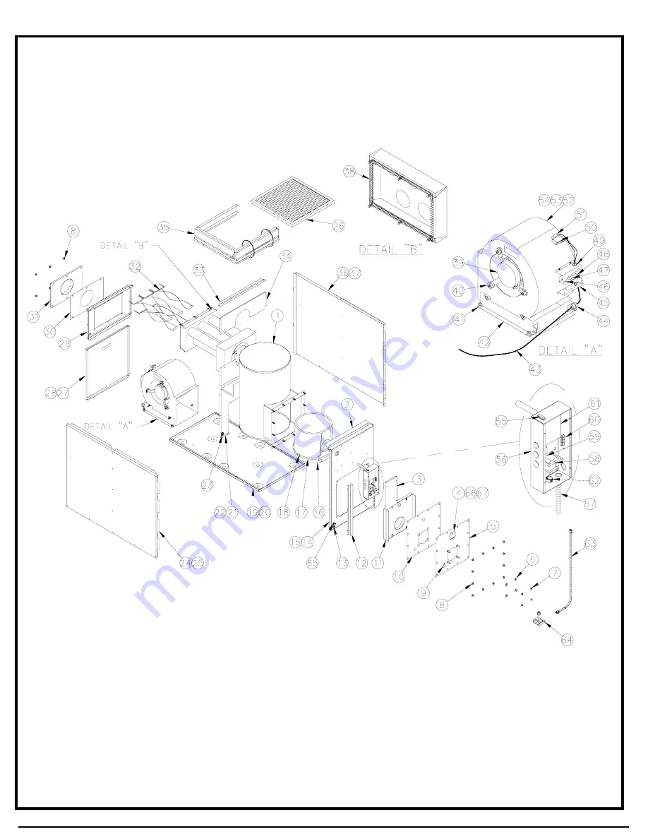
Page 21: ...22 PARTS LIST Model MBO115DABR D B50040B 445 01 4054 06...

Page 22: ...B40492 Top rear panel 30 B40032 Gasket smoke outlet 31 B40046 Smoke outlet assembly 32 B40054 01 Baffle assembly 5 required 33 B40043 Plenum divider 34 B40076 Top division panel 35 B40410 Filter rack...

Page 23: ...PARTS LIST Model MBOV115DABR D B50041B 445 01 4054 06...

Page 24: ...ntral support rear baffle and item 32 included 32 B01291 02 Seal strip 3 required 33 B40131 02 Left side panel assembly Item 34 included 34 B40125 02 Left side panel insulation 35 L04G005 Bushing 1 3...

Page 25: ...26 PARTS LIST Model LBO125DABR13 D B50038C 445 01 4054 06...

Page 26: ...32 B40032 Gasket smoke outlet 33 B40046 Smoke outlet assembly 34 B40071 Inlet baffle 2 required 35 B40043 Plenum divider 36 B40054 01 Baffle assembly 5 required 37 B40108 Division panel assembly Centr...

Page 27: ...PARTS LIST Models LBO145DABR34 D OLR182A16C B50039F 445 01 4054 06...

Page 28: ...B40107 01 Blower door assembly Item 29 included 29 Z99F050 Door handle 30 B40497 Top rear panel 31 B40031 Gasket smoke outlet 32 B40047 Smoke outlet 33 B40054 02 Baffle assembly 7 required 34 B40043...

Page 29: ...PARTS LIST Model FLO115DABR C OLF140C12C B50042A 445 01 4054 06...

Page 30: ...rack 29 Z04F004 Paper filter 20 x 20 x 1 1 required 30 B40381 Blower door assembly Item 31 included 31 Z99F050 Acces door 32 B40356 Top back panel assembly 33 Z04F001 Paper filter 10 x 20 x 1 1 requir...

Reviews: