GWA
Gas-Fired Water Boilers –
Boiler Manual
18
Part Number 670 01 1001 00
7
Checkout procedure
❏
Boiler and heat distribution units filled with water?
❏
Automatic air vent, if used, open one full turn?
❏
Air purged from system?
❏
Air purged from gas piping? Piping checked for leaks?
❏
Correctly-sized manifold orifices installed? See Table 3,
page 6, to check size and fuel type.
Correctly sized manifold orifices must be used.
Failure to do so will cause severe personal injury,
death or substantial property damage.
❏
Followed “Lighting or Operating Instructions” on boiler or in
Manual Section 9 or Control Supplement for proper start-up?
❏
Proper burner flame observed? See “Verify operation”, Manual
Section 6, page 17.
❏
Test limit control — While burners are operating, move indicator
on limit control below actual boiler water temperature. Burners
should go off while circulator continues to operate. Raise setting
on limit control above boiler water temperature and burners
should reignite.
❏
Test additional field-installed controls — If boiler has a low water
cutoff, additional high limit or other controls, test for operation
as outlined by manufacturer. Burners should be operating and
should go off when controls are tested. When controls are
restored, burners should reignite.
❏
Button on spill switch pushed in?
❏
Test ignition system safety device:
a. Standing pilot — Turn gas cock knob to PILOT position
and extinguish pilot flame. Pilot gas flow should stop in less
than 3 minutes. Put system back into operation (see
Section 6, pages 15-17).
b.
Spark-ignited pilot — Connect manometer to outlet side
of gas valve. Start boiler, allowing for normal start-up cycle
to occur and main burners to ignite. With main burners on,
manually shut off gas supply at manual main shutoff gas
valve. Burners should go off. Open manual main shutoff
gas valve. Manometer should confirm there is no gas
flow. Pilot will relight, flame sensing element will sense
pilot flame and main burners reignite.
❏
Set limit control(s) to system temperature requirements.
Adjust balancing valves and controls to provide design
temperature to system.
❏
For multiple zones, adjust flow so it is about the same in
each zone.
❏
Verify thermostat heat anticipator (if available) set properly?
See “Field wiring”, Manual Section 5, page 14, “Thermostat”.
❏
Cycle boiler with thermostat — Raise to highest setting and
verify boiler goes through normal start-up cycle. Lower to lowest
setting and verify boiler goes off.
❏
Measure natural gas input:
a. Operate boiler 10 minutes.
b.
Turn off other appliances.
c. At natural gas meter, measure time (in seconds) required
to use one cubic foot of gas.
d. Calculate gas input:
3600 x 1000
number of seconds from step c
= Btuh
e. Btuh calculated should approximate input rating on boiler
rating label.
o
Installation instructions have been followed.
o
Checkout sequence has been performed.
o
Above information is certified to be correct.
o
Information received and left with owner/maintenance person.
Installation and service certificate
❏
Check manifold gas pressure by connecting manometer to
downstream test tapping on main gas valve. Manifold pressure
for natural gas should be 3.5" w.c. and for propane gas should
be 10" w.c.
❏
Observe several operating cycles for proper operation.
❏
Set room thermostat to desired room temperature.
❏
Fill in Installation and service certificate below?
❏
Review all instructions shipped with this boiler with owner or
maintenance person. Return instructions to envelope and give
to owner or place in pocket inside front panel in boiler.
Boiler model
_______________________________________________________________
Series
____________
CP number
_______________________________________
Date installed
_________________________________
Measured Btuh input
____________
Installer
_______________________ ______________________________ ____________________________
(company)
(address)
(phone)
_____________________________________
(installer’s signature)
GWA
Gas-Fired Water Boilers –
Boiler Manual
19
Part Number 670 01 1001 00
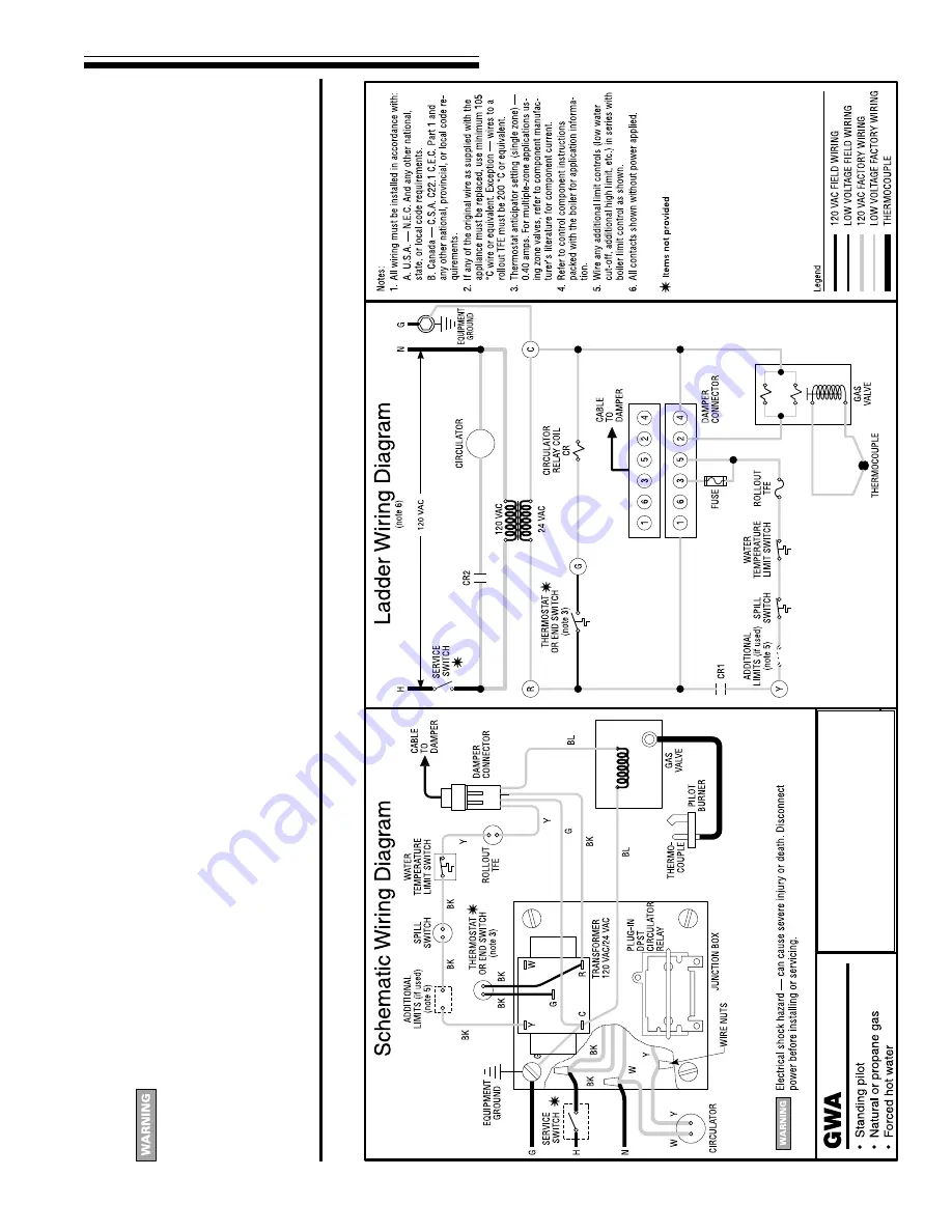
Figure 14
Wiring diagram
—
Standing pilot system
8
Sequence of operation
—
standing pilot boilers
Follow all procedures given in this manual and
“Lighting Instructions
” when
oper
ating the boiler
. F
ailure to do so could result in se
v
ere personal injur
y,
death or substantial proper
ty damage
.
1.
Standby mode:
After pilot is manually lighted, the gas valve provides pilot gas and
maintains pilot as long as the thermocouple is satisfied. If thermocouple signal drops
for any reason, pilot must be manually lighted, following the
“Lighting Instructions
” in
this man
ual and on boiler
. V
ent damper will remain closed until a call f
or heat.
2.
Call f
or heat:
When ther
mostat circuit closes
, the boiler circulator and v
ent damper
are energiz
ed.
The v
ent damper dr
iv
es open.
When the v
ent damper is fully open, its
end s
witch energiz
es the main gas v
alv
e
.
This pro
vides gas to the main b
u
rners
.
Burners remain ignited until thermostat circuit or limit circuit opens. Burners and
circulator are de-energized when call for heat stops. Burners are de-energized, but
circulator remains on, if the limit circuit opens.
3.
Limit operation:
When a limit control opens
, the main gas v
alv
e is de-energiz
ed, b
u
t
circulator contin
ues to r
un.
When the limit circuit closes again, the main gas v
alv
e is
energized if there is still a call for heat.
4.
Thermostat heat anticipator:
Set heat anticipator as shown on wiring diagram,
Figure 14.


