Maintenance, troubleshooting, spare parts and dismantling
iDRY iRDP CT 20-500
33
Prior to carrying out maintenance works at the dryer, switch it off and wait for at least 30 minutes.
Caution!
Hot surfaces!
During operation, several components can reach surface temperatures of more than 140°F (60°C).
There is the risk of burns.
All components concerned are installed inside of the closed housing. The housing must only be opened
by certified skilled personnel.
Some components can reach high temperatures during operation. Avoid any contact until the system or
the component has cooled down.
FAULT POSSIBLE
REASON
– SUGGESTED MEASURE
The display of DMC51
is not lit
Verify that the system is powered.
Verify the electric wiring.
If installed – HPS pressure switch has been activated – see specific point
iRDP CT 200-500 3phase - Blow of fuse (FU2 on the electric diagram) of the auxiliary
circuit - replace it and check the proper operation of the dryer.
iRDP CT 200-500 3phase – The remote control is OFF (see contact on terminals 1-2
on electric diagram)
The compressor does
not work.
If ESS=YES (see section 8.12.7) – the Dew Point displayed on DMC51 is sufficiently
low, the led
is OFF, so the compressor is not active – wait that the temperature
becomes higher.
Activation of the compressor internal thermal protection – wait 30 minutes and then
retry.
Verify the electric wiring.
If installed – the KC relay is faulty – replace it
If installed – replace the internal thermal protection and/or the start-up relay and/or
the start-up capacitor and/or the working capacitor.
DMC51 – The led
is ON – see specific point.
If the compressor still does not work, replace it.
If ESS=YES (see
section 8.12.7) - The
compressor remains
OFF unexpected short
time.
The OFF time of the compressor is related to the actual dryer thermal load. If dryer is
running in low or no-load conditions and at mild/low ambient temperatures, and the
compressor remains OFF for too short time (less than 3-5 minutes), check which of the
following reasons is creating the malfunction:
1. The DewPoint probe T1 doesn’t correctly detect the temperature - ensure the sensor
is pushed into the bottom of probe well.
2. The thermal insulation of DewPoint probe T1 is damaged – restore the thermal
insulation
3. The ambient temperature is too high or the room aeration is insufficient - provide
proper ventilation.
4. The solenoid valve EVL is not operating correctly - see specific point.
5. If installed - The check valve CHV is jammed (open) - contact a ICP service
technician to replace it.
The fan of the
condenser does not
work
Verify the electric wiring.
PV pressure switch is faulty. Contact a ICP service technician.
iRDP CT 200-500 3phase- Blow of fuse (FU1-FU2 on the electric diagram) - replace it
and check the proper operation of the dryer.
There is a leak in the refrigerant circuit – contact a ICP service technician.
If the fan still does not work, replace it.
Summary of Contents for iDRY iRDP CT 100
Page 29: ...Technical data iDRY iRDP CT 20 500 29 11 2 Technical data iDRY iRDP CT 20 500 2 1 230 60...
Page 38: ...Maintenance troubleshooting spare parts and dismantling 38 iDRY iRDP CT 20 500...
Page 39: ...Maintenance troubleshooting spare parts and dismantling iDRY iRDP CT 20 500 39...
Page 42: ...Appendices 42 iDRY iRDP CT 20 500 13 1 2 Dryer dimensions iDRY iRDP CT 75...
Page 43: ...Appendices iDRY iRDP CT 20 500 43 13 1 3 Dryer dimensions iDRY iRDP CT 100 150...
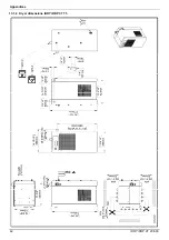
Page 44: ...Appendices 44 iDRY iRDP CT 20 500 13 1 4 Dryer dimensions iDRY iRDP CT 200 250...
Page 45: ...Appendices iDRY iRDP CT 20 500 45 13 1 5 Dryer dimensions iDRY iRDP CT 300 350...
Page 46: ...Appendices 46 iDRY iRDP CT 20 500 13 1 6 Dryer dimensions iDRY iRDP CT 400 500...
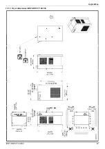
Page 47: ...Appendices iDRY iRDP CT 20 500 47 13 1 7 Dryer dimensions iDRY iRDP CT 200 250 3phase...
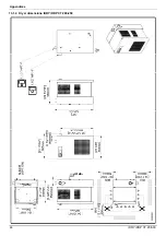
Page 48: ...Appendices 48 iDRY iRDP CT 20 500 13 1 8 Dryer dimensions iDRY iRDP CT 300 350 3phase...
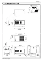
Page 49: ...Appendices iDRY iRDP CT 20 500 49 13 1 9 Dryer dimensions iDRY iRDP CT 400 500 3phase...
Page 51: ...Appendices iDRY iRDP CT 20 500 51 13 2 2 Exploded diagram iDRY iRDP CT 20 30...
Page 52: ...Appendices 52 iDRY iRDP CT 20 500 13 2 3 Exploded diagram iDRY iRDP CT 50...
Page 53: ...Appendices iDRY iRDP CT 20 500 53 13 2 4 Exploded diagram iDRY iRDP CT 75...
Page 54: ...Appendices 54 iDRY iRDP CT 20 500 13 2 5 Exploded diagram iDRY iRDP CT 100...
Page 55: ...Appendices iDRY iRDP CT 20 500 55 13 2 6 Exploded diagram iDRY iRDP CT 125 150...
Page 56: ...Appendices 56 iDRY iRDP CT 20 500 13 2 7 Exploded diagram iDRY iRDP CT 200 250...
Page 57: ...Appendices iDRY iRDP CT 20 500 57 13 2 8 Exploded diagram iDRY iRDP CT 300 350...
Page 58: ...Appendices 58 iDRY iRDP CT 20 500 13 2 9 Exploded diagram iDRY iRDP CT 400 500...
Page 59: ...Appendices iDRY iRDP CT 20 500 59 13 2 10 Exploded diagram iDRY iRDP CT 200 250 3phase...
Page 60: ...Appendices 60 iDRY iRDP CT 20 500 13 2 11 Exploded diagram iDRY iRDP CT 300 350 3phase...
Page 61: ...Appendices iDRY iRDP CT 20 500 61 13 2 12 Exploded diagram iDRY iRDP CT 400 500 3phase...


