13
443 06 2403 01
Specifications subject to change without notice.
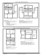
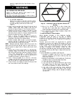
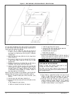
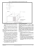
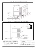
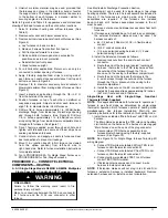
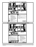
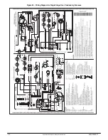
Figure 13
−
Auxiliary Door Switch
Two
−
Stage Heat with Two
−
stage Gas
−
Heat Thermostat
(Field Supplied)
NOTE
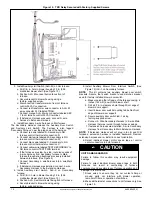
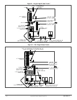
: ALL thermostat connections are to be made to LH
furnace control ONLY. (See Figure 16)
NOTE
: This application allows only the LH furnace to operate
for first
−
stage heat mode or both furnaces to operate for
second
−
stage heat mode as determined by a two
−
stage
thermostat. See furnace Installation, Start
−
Up, and Operating
Instructions for further details on this heating mode.
To operate furnaces in two
−
stage heating mode when a
two
−
stage thermostat controls the staging, install twinning kit
as described in Single
−
Stage Heat with Single
−
Stage Gas
Heat Thermostat, then modify TKR wiring as follows:
a. Disconnect TKR white wire labeled W from the LH
furnace control thermostat connection W.
b. Cut off terminal of TKR white wire labeled W and
strip 1/4 in. (6 mm).
c. Connect two
−
stage thermostat W2 connection to
TKR white wire labeled W.
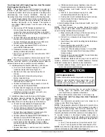
PERSONAL INJURY HAZARD
Failure to follow this caution could result in intermittent
furnace operation and unit damage.
Supply
−
air temperature will be uneven left
−
to
−
right
when only main system is operating.
CAUTION
!
NOTE
: ALL other two
−
stage thermostat connections are to be
made to LH furnace control ONLY. (See Figure 16)
B. All Two
−
Stage Models: F8MTL & G8MTL Two
−
Speed
Non
−
Condensing HSI Furnaces with PSC Motors
See Electrostatic Discharge Precaution Section.
The twinning kit can be used for single
−
stage or two
−
stage
heating operation. There are 3 harness assemblies included in
this kit. If the furnaces are side
−
by
−
side, only 2 harness
assemblies are required. If the furnaces are installed
back
−
to
−
back, all 3 harness assemblies included in the kit
must be used.
FIRE HAZARD
Failure to follow this warning could result in fire,
personal injury or death.
Make no connections between the R 24
−
vac connector
in 1 furnace and the R 24
−
vac connector in other
furnace.
!
WARNING
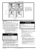
1. Remove outer doors and blower access doors from both
furnaces.
2. If furnaces are installed back
−
to
−
back in any orientation,
the external Extension Harness must be used. The
harness consists of:
a. 54
−
1/2
−
in. of 1/2
−
in. flexible steel conduit
b. (2) 90
_
conduit connectors
c. (2) 4 wire polarized wiring harness
d. (2) 2 wire polarized wiring harness
3. Install the Extension Harness as follows:
a. Remove lock nuts from the end of each conduit
connector.
b. Route the end of the harness labeled “Twinning Kit
Harness” that mates to the TKR relay harness from
the outside of the furnace through the 7/8
−
in.
knock
−
out in the casing to the blower compartment.
c. Route the end of the harness that mates to the
4
−
wire harness through the outside of the furnace
through the 7/8
−
in. knockout in the casing to the
blower compartment.
d. Install the lock nuts on the 90
_
conduit connectors.


