7
443 06 2403 01
Specifications subject to change without notice.
opening in appropriate side of each furnace. (See
UNIT DAMAGE AND FIRE HAZARD
Failure to follow this warning could result in unit
damage, fire, personal injury or death.
DO NOT use the side of the furnace for return
−
air duct
connections, as limit cycling will occur.
!
WARNING
b. For downflow applications:
Return air can only be connected to bottom opening
of furnace. A common return air plenum is required
for proper auxiliary limit switch operation. (See
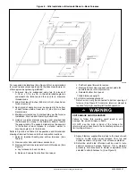
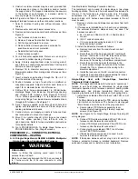
5. Apply 2 factory
−
supplied foam strips to the back of each
furnace. Locate strips equal distance from top and
bottom as shown in Figure 5. Trim off excess material.
6. Determine which side of furnace will be used to route
external extension harness. Remove 7/8
−
in. diameter
accessory hole knockouts in blower compartment side
selected to attach harness to. (See Figure 3)
7. Bend or remove the supply flanges as required for
upflow or downflow installation. Refer to the furnace
installation instructions for complete details.
8. Position furnaces back
−
to
−
back on return
−
air plenum,
supply air plenum or evaporator coil casing. Adjust and
shim each furnace to align both furnaces.
NOTE
: External extension harness cannot be used on the
same side of the furnace that the return air ducts connect to.
Locate harness on opposite side of furnace when side return
air is used.
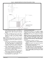
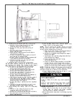
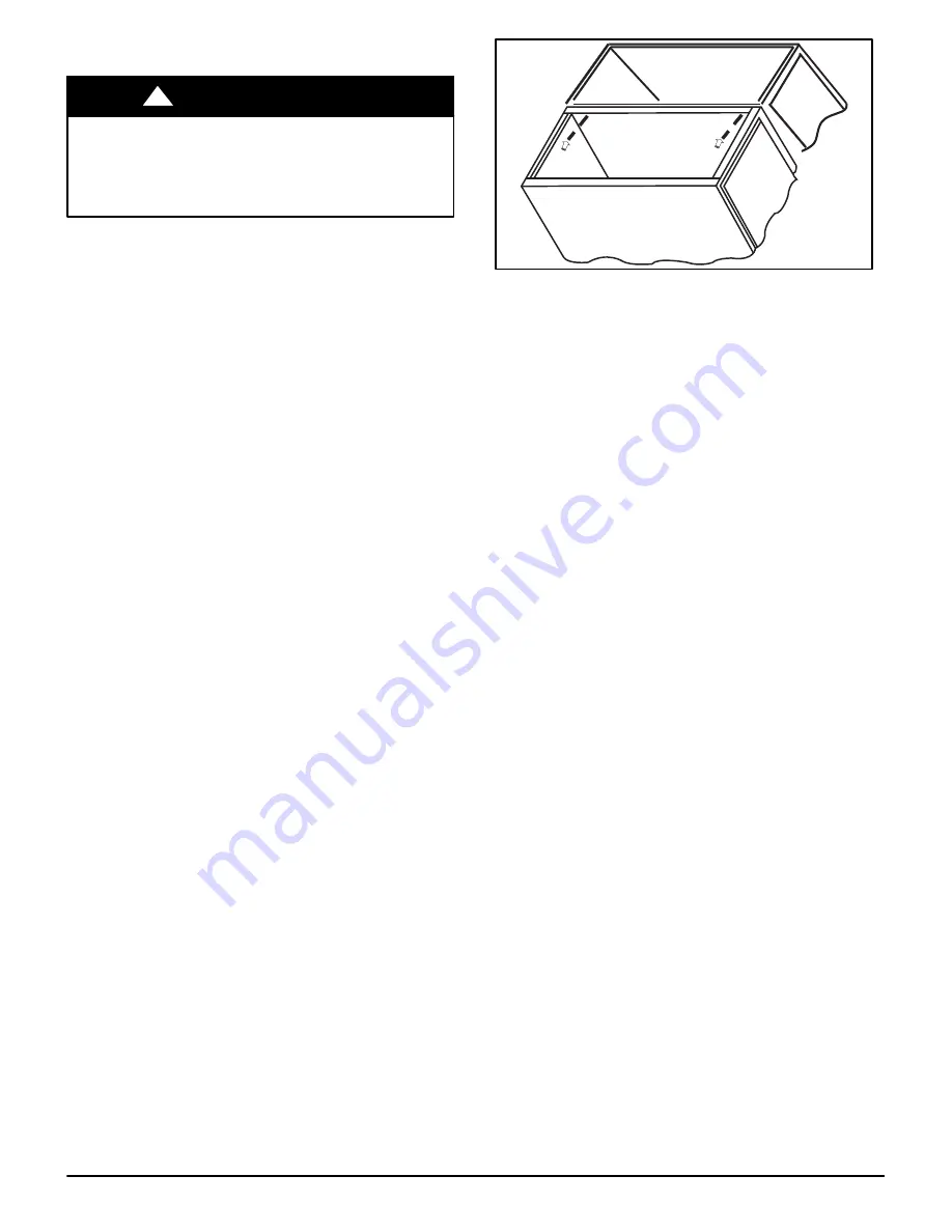
9. Drill two 1/8
−
in. holes, approximately 1 in. (25 mm)below
discharge flange, from inside top of discharge opening
and through both furnaces. (Similar to Figure 6) Drill two
1/8
−
in. holes, approximately 1 in. (25 mm)below return
air flange, from inside top of return air opening and
through both furnaces. (Similar to Figure 7)
10. Drive 1 factory
−
supplied No. 6 X 3/4
−
in. LG screw
through each hole and tighten until furnaces are secure
and foam strips have sealed gap between furnaces.
11. Connect return
−
and supply
−
air ducts to furnaces. Seal
duct connections to prevent air leakage.
A02219
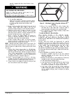
Figure 7
−
Attaching Furnaces Together at Return Air
Opening
12. Move 115
−
v junction box JB in either furnace from
left
−
hand side to right
−
hand side if required. Refer to
furnace installation instructions for complete details.
13. Go to Step 2A for Single Stage Furnaces or Step 2B for
Two
−
Stage Furnaces.
C. Horizontal, Back
−
to
−
Back Position
When twinning furnaces in the horizontal position,
consideration must be made to the type of building
construction. Attic floors should be constructed to support
normal live and dead loads of the furnaces and the person(s)
servicing them.
Trusses, wood and metal are engineered for specific
applications, and may not support the weight of two (2)
furnaces suspended from the top chords or the bottom chords
of the trusses. Long horizontals spans may flex or sag,
resulting in damage to the building. Contact the truss
manufacturer for additional design and engineering assistance.
Do not suspend furnaces with straps or suspend furnaces from
roof decking.
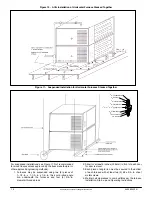
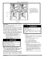
For attic installations on a platform (See Figure 8):
1. Construct a platform from 3/4
−
in. (76 mm) (nominal
plywood), extending out 30 inches (762 mm) from the
front of each furnace.
2. Maintain all clearances to combustibles per the furnace
Installation, Start
−
up and Operating Instructions.
3. Follow all additional building codes.
4. Long truss spans may require additional support along
the bottom chord of the truss. Consult the truss
manufacturer’s guidelines for engineering assistance.
5. Long rafter or attic joist spans may require additional
support along the bottom of the rafter or joist. Consult
local or regional building codes for design and loading
requirements.


