ROCKY-3702EV Socket 370 Celeron
TM
& Pentium III
with AGP VGA & 10/100Mbps Ethernet SBC
40
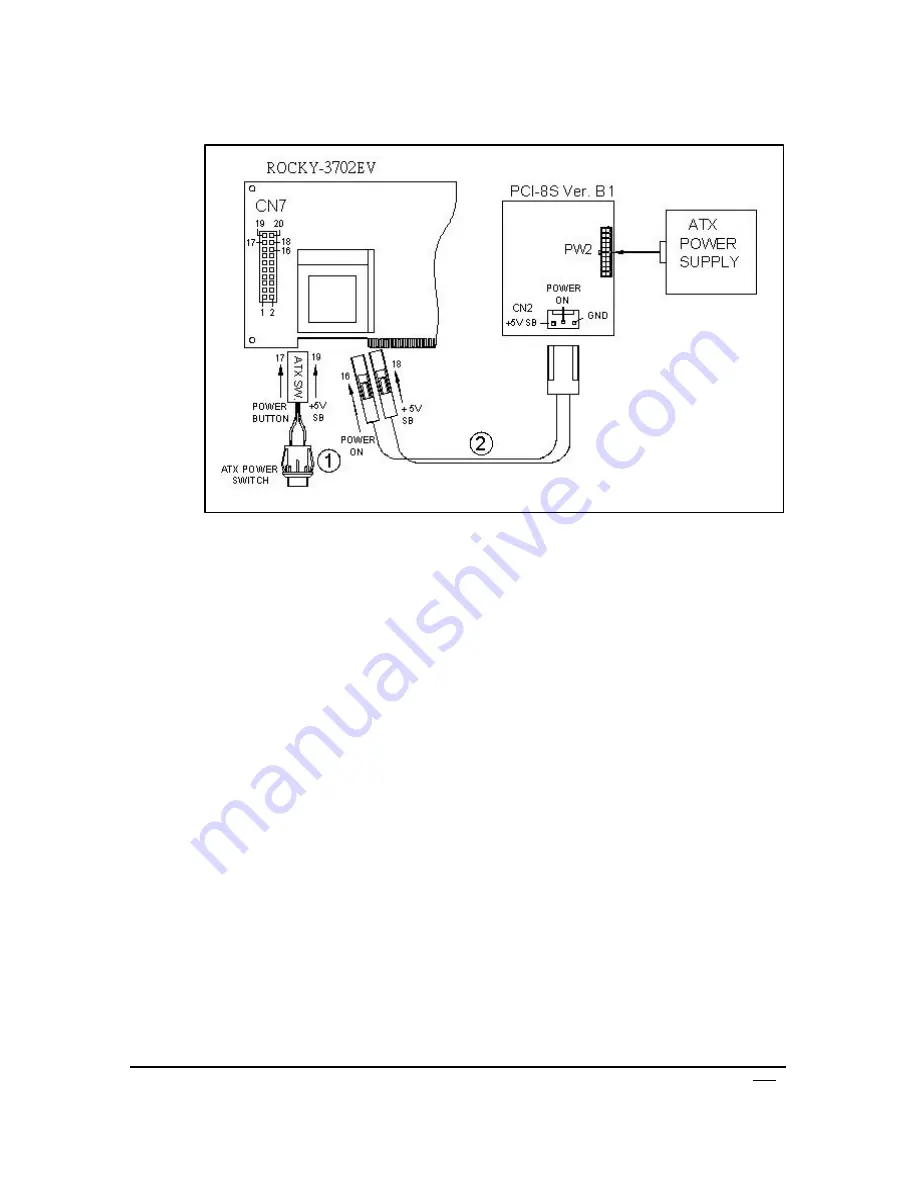
2.4. ROCKY-3702EV (through Power Button & +5VSB):
Connect the ATX power supply switch to the pin 17 (power
button) and pin 19 (+5VSB) of CN7 (multi panel) on the board.
If you wish to turn off the power supply, please push the ATX
power switch button for about 4 sec. And to turn ON the system,
simply push the button once.
B. For the backplanes without ATX connector.
Refer to the following figure, please follow the steps below:
1. Please disconnect the AC cord of the Power Supply from the AC
source to prevent sudden electric surge to the board.
2. Connect the ATX Power Switch to the pin 9 (power button) and 19
(+5VSB) of J1 in the Rocky-P218A ISBC.
3. Connect the ATX Power Switch to the pin 9 (power button) and 19
(+5VSB) of J1 in the Rocky-P218A ISBC(Type A connection)
Note : Some boards are Type B connection (through Power Button and GND).
4. Connect the green cable from the cable kit to the pin 18 (power ON)
of J1 in the Rocky-P218A ISBC and connect the purple cable to the
pin 20 (+5VSB) of J1.
Summary of Contents for ROCKY-3702EV
Page 2: ......


