EtherCAT to Modbus RTU Gateway
Copyright © 2017 ICP DAS CO., Ltd. All Rights Reserved.
-
16 -
3.2
Connecting the Power and the Host PC
Step 1
Connect both the IN port of ECAT-2610 module and RJ-45 Ethernet port
of Host PC.
Ensure that the network settings on the Host PC have been correctly configured and are functioning
normally.
Ensure that the Windows firewall or any Anti-Virus firewall is properly configured to allow
incoming connections, or temporarily disable these functions.
NOTE
Step 2
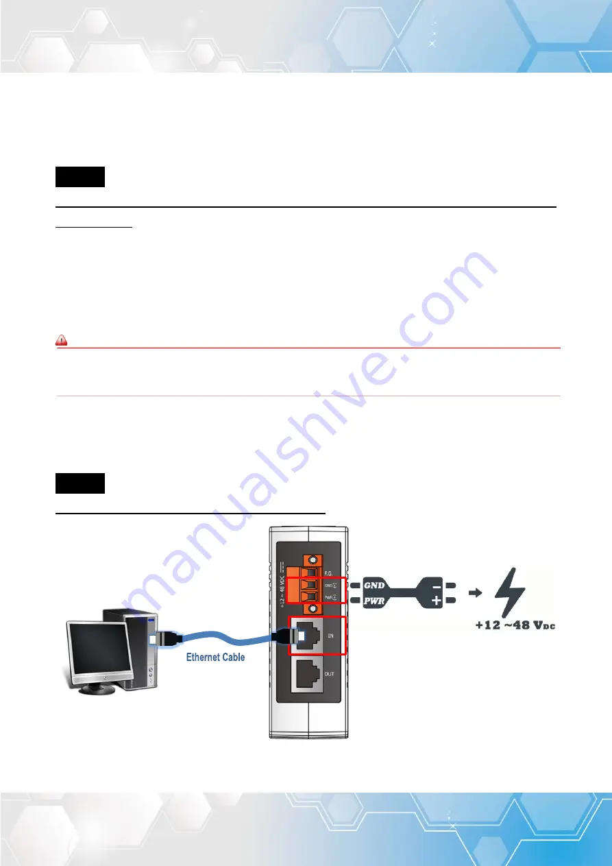
Apply power to the ECAT-2610 module
Connect the
PWR(+)
pin to positive
terminal on a
+12 ~ +48 V
DC
power
supply, and connect the
GND(-)
pin to
the
negative terminal
.
Connect the Host device to the
IN Port
on ECAT-2610 module.
Attaching an ESC (EtherCAT Slave Controller) directly to an office network will result in network flooding, since the ESC
will reflect any frame – especially broadcast frames – back into the network (broadcast storm)
.
Figure 3-2.1


