EtherCAT to Modbus RTU Gateway
Copyright © 2017 ICP DAS CO., Ltd. All Rights Reserved.
-
32 -
4.3
Testing Modbus RTU Device
Before beginning the “Test Modbus RTU Device” process, the configuration file and upload to the
ECAT-2610 module must first be fully completed, refer to
Section 4.2 “Configuring and Uploading”
more detail.
NOTE
The testing method depends on your Modbus RTU device. Here, the M-7050D module is used as an example. For other
Modbus RTU device, refer to the specific Quick Start Guide or User Manual for that Modbus RTU device.
Step 1
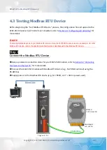
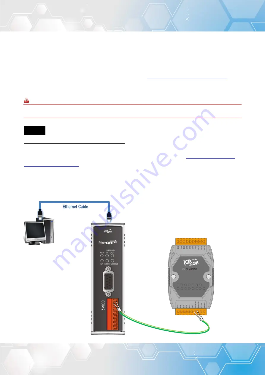
Connect the Modbus RTU Device.
Keep up network connection status for your ECAT-2610 module, refer to
Connect the ECAT-2610 module with Modbus RTU device (e.g., M-7050D, optional) using the
RS-485 bus.
Supply power to the Modbus RTU device (e.g., M-7050D, +10 ~ +30 V
DC
power used).
Figure 4-3.1
RS-485 Wiring
Power Supply
M-7050D
7-ch DI & 8-ch DO
+10 ~+30 V
DC

