EtherCAT to Modbus RTU Gateway
Copyright © 2017 ICP DAS CO., Ltd. All Rights Reserved.
-
7 -
2.
Hardware Information
2.1
Appearance
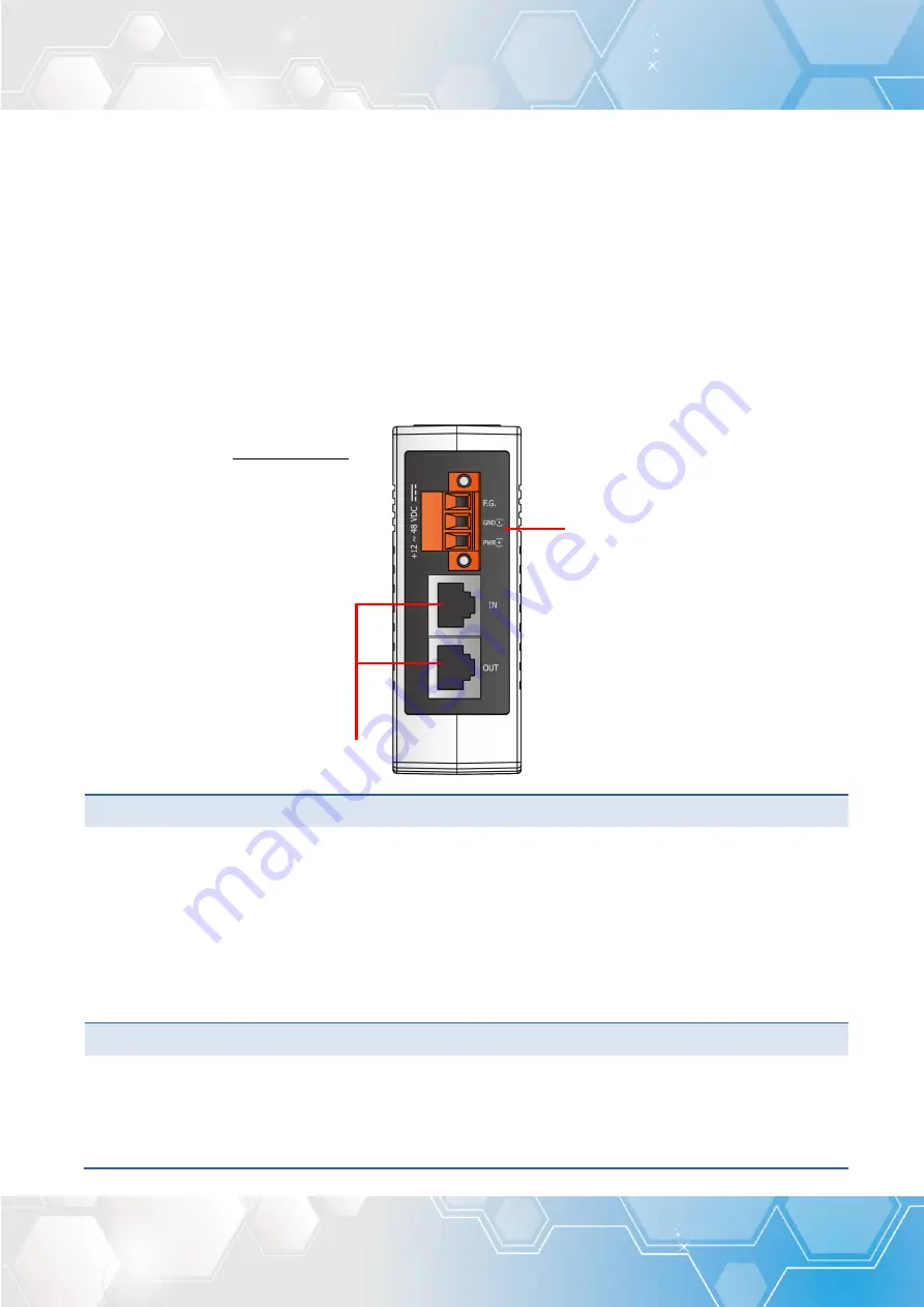
The front panel and top panel of the ECAT-2610 module contain the Modbus COM Port, PC COM
port, LEDs, Ethernet Port and power connector.
Top Panel
1.
DC Power Input Connector
The
“PWR(+)”
and
“GND(-)”
pins are used for the power supply applies to all types of ECAT-2610
module. The valid power voltage range is from
+12 to +48 V
DC
.
The definition of
“F.G.”
(Frame Ground)
: Electronic circuits are constantly vulnerable to
Electrostatic Discharge (ESD), which becomes worse in a continental climate area. ECAT-2610
module feature a new design for the frame ground, which provides a path that bypasses ESD,
resulting in an enhanced ESD protection capability and ensuring that the module is more reliable.
2.
EtherCAT Interface
ECAT-2610 module is equipped with two RJ-45 EtherCAT Interface ports.
IN
is EtherCAT signal input
port that connect EtherCAT Master or EtherCAT signal output of previous EtherCAT slave module
,
OUT
is EtherCAT signal output that connect the next EtherCAT signal input of EtherCAT slave
module.
1. DC Power
Input Connector
2. EtherCAT Interface
Figure 2-1
Top panel of ECAT-2610


