background image


9

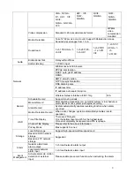
VGA

QVGA


D1

HD1

CIF

QCIF


QVGA

QQVGA

720 

HD1

CIF

QCIF

QQVGA 
 

QCIF

QQVGA 

QCIF


QVGA

QQVGA 
 

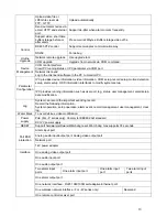
Video compression  

Standard H.264 encode/decode format 

MPEG4 
video 
compression 
standard 

Motion Detection 

Take 18*22 pix as a macro unit. Support 396 detection zones. 
Sensitivity level ranges from 1 to 6. 

Dual-stream  

1-ch 15f UXGA

1-

ch CIF 

1-ch 25f 720

1-ch HD1 

1-ch 25f D1

1-ch 25f 

CIF 

1-ch 12.5f 
UXGA

1-

ch 

12.5f CIF 
 

Bidirectional Talk  

Delay within 200ms 

Audio  

Audio Listening  

1-ch MIC input.  

WEB access via IE browser. 

PPPoE  dial function 
DHCP  auto get IP address 
DDNS 
SMTP  email function 
NTP time synchronization. 
DNS domain parse 
IP address filter 

IP address auto search function 

Network  

Wireless Network Interface :802.11b/g 

N/A 

Schedule Record  

Support max 6 periods.  

Manual Record  

After enabling manual record, no matter system is in schedule or 
alarm status or not, system just begins recording.  

Alarm Record  

System automatically enables recording function when alarm 
occurred. 

Record  

Motion Detection Record  

When video changes, system automatically enables record 
operation.  

Time Title Display  

There are 255 layers.  
O is the bottom layer and 255 is the highest layer. 
O means completely transparent and 255 is opaque. 

Channel Title Display


Please refer to the above information.  

OSD 

Privacy Mask  

Max supports 8 zones. 

Local SD storage 

Support high-speed card/low-speed card 

Based on SDK network 
storage 

Storage 

Based on FTP network 
storage 

Supported  

Network alarm/local 
alarm output 

1-ch local/network alarm output 

Alarm 

Local alarm/network 
alarm input  

1-ch local/network alarm input 

Event 

Management 

Activate alarm via motion 
detection or external 
input 

Please enable pre-record function when activating  the alarm 

Summary of Contents for F Series

Page 1: ...F Series Indoor IP Camera User s Manual For F725 F726 F715 F665 F645 F625 series only ...

Page 2: ...our IP camera This user s manual is designed to be a reference tool for your system Please read the following safeguard and warnings carefully before you use this series product Please keep this user s manual well for future reference ...

Page 3: ... not apply power to the IP camera before completing installation Do not put object on the IP module 3 Environment This series IP camera should be installed in a cool dry place away from direct sunlight inflammable explosive substances and etc Please open the accessory bag to check the items one by one in accordance with the list below Contact your local retailer ASAP if something is missing or dam...

Page 4: ...9 2 3 Lens 19 2 4 Remote Control 20 2 5 Bidirectional talk 21 2 5 1 Device end to PC end 21 2 5 2 PC end to the device end 22 3 Installation 23 3 1 Lens Installation 23 3 1 1 Auto Aperture Lens 23 3 1 2 Manual Lens 23 3 1 3 Remove Lens 24 3 1 4 SD Card Installation 24 3 1 5 Remove SD card 25 3 1 6 3G Card Installation 26 3 1 7 Remove 3G card 27 3 1 8 I O Port 27 4 System Network 29 4 1 General Net...

Page 5: ...on 33 6 1 Network Connection 33 6 2 Login and Main Interface 33 7 GUI Operation 36 7 1 Main Menu 36 7 2 Network Setup 36 7 3 Encode Setup 37 8 Wireless Network Access Setup For W Series Only 39 8 1 Wireless Router Setup 39 8 2 IPC Web Network Setup 40 8 3 Web Setup 41 9 FAQ 42 ...

Page 6: ... can support the wireless data transmission z Support cable network data transmission via Ethernet Storage Function z Support central server backup function in accordance with your configuration and setup in alarm or schedule setting z Support record via Web and the recorded file are storage in the client end PC z Support local SD card hot swap Please note SD card can only memorize the image Alarm...

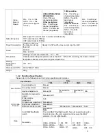
Page 7: ...ion 1 3 1 Performance Please refer to the following sheet for IPC performance specification Specification Name IPC F726 IPC F725 IPC F715 IPC F6X5 Standard PAL 1f s 12 5f s NTSC 1f s 15f s Now it max supports 12 5f s PAL 1f s 25f s NTSC 1f s 30f s Encode capacity One 720 one HD1 One 720 one HD1 One 720 one HD1 One D1 one CIF Video Encode Bit Stream Main stream UXGA 1600 1200 Extra stream D1 704 57...

Page 8: ...ure Chassis internal rising temperature is less than 20 When IPC is working the chassis internal temperature deducts environment original temperature Working Environment Humidify 10 90 Dimension H W D 58mm 69mm 139mm Weight 500g 1 3 2 Function Specification Please refer to the following sheet for function specification information Note Specification F725 F715 F6X5 F726 Zoom Adjustment Manual Focus...

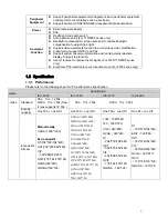
Page 9: ...eriods Manual Record After enabling manual record no matter system is in schedule or alarm status or not system just begins recording Alarm Record System automatically enables recording function when alarm occurred Record Motion Detection Record When video changes system automatically enables record operation Time Title Display There are 255 layers O is the bottom layer and 255 is the highest laye...

Page 10: ...setup Parameter Configuration IPC provides running information such as user port log status user management email setup date modification Log System can record the important event log record Record the following information System operation setup operation alarm event record management user management clear log Water Mark To avoid vicious video modification PoE For P series only Comply to IEEE802 ...

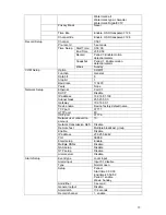
Page 11: ... Type Item Name F726 F725 F715 F6X5 Date format Y M D DST Disable by default Date separator _ Time format 24H Language Simplified Chinese When HDD is full Overwrite Record duration 60M Device No 8 General Setup Video type PAL Channel Channel01 Encode mode MPEG4 H 264 H 264 H 264 Audio Video enable Enable audio and video General bit stream General bit stream Resolution UXGA 720 720 D1 Frame rate 25...

Page 12: ... Disable IP address 192 168 1 108 Subnet mask 255 255 0 0 Gateway 192 168 0 1 Device name Device factory default name TCP port 37777 HTTP port 80 UDP port 37776 Network user connection amount 10 Network transmission QoS Disable Remote host Multiple broadcast group Enable Disable IP address 239 255 42 42 Port 36666 Email setup Enable Multiple DDNs Disable NAS setup Disable NTP setup Disable Network...

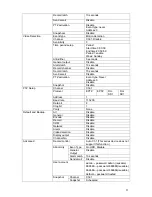
Page 13: ...pshot Disable Channel Ch01 Protocol EPTZ EPTZ DH SD1 DH SD1 Address 1 Baud rate 115200 Data bit 8 Stop bit 1 PTZ Setup Parity None All Disable General Disable Encode Disable Record Disable COM Disable Network Disable Alarm Disable Video detection Disable Display output Disable Default and Backup Channel No Disable Record control Auto Ch1 This series device does not support this function Even Type ...

Page 14: ... Day Night Mode Color Backlight Compensation Disable Auto Aperture N A N A Disable Disable White Balance N A Signal Type Internal input Mirror Disable Disable N A N A Camera Property Flip Disable Disable N A N A Enable Disable SN 1 IP 0 0 0 0 Port 7000 Auto Registration Device ID Dahua DNS 202 101 172 35 DNS Setup Alternative DNS 202 101 172 35 ...

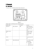
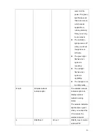
Page 15: ...n Interface Name Connector Function VIDEO OUT Video output port BNC Output analog video signal Can connect to TV monitor to view video Wireless Antenna Port Connect to wireless antenna to receive WIFI 3G wireless signal DC 12V Power port Input 12V DC STATUS Status indication light It is to indicate camera working status z The red light becomes on when connect the ...

Page 16: ...re z The green light flashes when system is recording z The red light flashes when system is upgrading z The red light is on in safety mode WLAN Wireless network indication light The wireless network indication light is to display wireless network working status The network indication light becomes green when you connect the IP camera to the wireless network A RS485 port I O port RS485_A port cont...

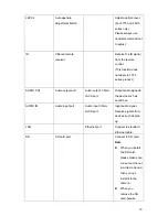
Page 17: ...C 1 ch alarm output Alarm output port To output alarm signal to the alarm device NO Normal open alarm output end C Alarm output public end RX RS232_RX RS232 receive end TX Transparent debug serial port RS232_TX RS232 COM send out end G GND Ground end RESET RESET button Restore factory default setup When system is running normally power indication light is green press the RESET button for at least ...

Page 18: ...O OUT Audio output port Audio output 3 5mm JACK port Output audio signal to the device such as sound box AUDIO IN Audio input port Audio input 3 5mm JACK port Input audio signal Receive signals from devices such as pick up LAN Ethernet port Connect to standard Ethernet cable SD SD card port Connect to SD card Note z When you install the SD card please make sure current card is not in write mode an...

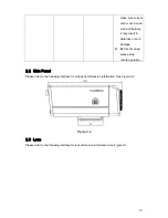
Page 19: ... loss or card damage z Before hot swap please stop record operation 2 2 Side Panel Please refer to the following interface for side panel dimension information See Figure 2 2 Figure 2 2 2 3 Lens Please refer to the following interface for lens dimension information See Figure 2 3 ...

Page 20: ...e refer to the following interface for remote control information See Figure 2 4 Figure 2 4 Please refer to the following sheet for detail information Icon Name Function Reset device Reserved for future use Emergency Reserved for future use ...

Page 21: ...irm current operation Cancel Cancel current setup Number 0 to number 9 Number password channel switch For number more than 10 Reserved Input method switch Reserved 2 5 Bidirectional talk 2 5 1 Device end to PC end Device Connection Please connect the speaker or the pickup to the first audio input port in the device rear panel Then connect the earphone or the sound box to the audio output port in t...

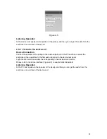
Page 22: ...ickup to the audio output port in the PC and then connect the earphone or the sound box to the first audio input port in the device rear panel Login the Web and then enable the corresponding channel real time monitor Please refer to the above interface Figure 2 5 to enable bidirectional talk Listening Operation At the PC end speak via the speaker or the pickup and then you can get the audio from t...

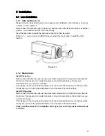
Page 23: ...the screw near the focal circle Then please turn counter clockwise to move the focal circle out for several millimeters Now you can focus manually Then please use the cross head screwdriver to fix the screw back firmly Secure the focal circle Finally line up lens to the proper installation Turn clockwise to fix the lens firmly Install CS type lens Remove the CCD protection cap use the cross head s...

Page 24: ...he CCD protection cap back to protect the CCD Figure 3 3 3 1 4 SD Card Installation Please follow the steps listed below to install SD card The interface is shown as in Figure 3 4 and Figure 3 5 Use the screwdriver to loosen the SD card protection screw in the rear panel and then remove the SD card protection cap from the camera Install the SD card to the camera according to the proper installatio...

Page 25: ...The interface is shown as Figure 3 6 Use the screwdriver to loosen the screw of SD card protection cap in the rear panel Remove the cap from the camera Follow the SD card direction to remove the SD card Insert the SD card protection cap Use the screwdriver to fix the screw to secure the protection cap ...

Page 26: ...ewdriver to loosen the 3G card protection cap screw in the side panel and then remove the 3G card protection cap from the camera Install the 3G SIM card to the camera according to the proper installation position Put the 3G card protection cap back Use the screwdriver to fix the 3G card protection cap screw firmly to secure the 3G card protection cap Figure 3 7 ...

Page 27: ...crewdriver to fix the screw to secure the protection cap Figure 3 9 3 1 8 I O Port Install Cable Please follow the steps listed below to install the cable See Figure 3 10 Use the small slotted screwdriver to press the corresponding button of cable groove Insert the cable into the groove and then release the screwdriver Remove Cable Please follow the steps listed below to remove the cable Use the s...

Page 28: ...28 Figure 3 10 ...

Page 29: ...29 4 System Network 4 1 General Network Please refer to Figure 4 1 for Wifi and general system connection Figure 4 1 4 2 3G Network Please refer to Figure 4 2 for 3G cable connection Figure 4 2 ...

Page 30: ...ol only applies to the IP addresses in the same segment 5 2 Operation Double click the ConfigTools exe icon you can see an interface is shown as in Figure 5 1 In the device list interface you can view device IP address port number subnet mask default gateway MAC address and etc Figure 5 1 Select one IP address and then right click mouse you can see an interface is shown as in Figure 5 2 ...

Page 31: ...gin interface Or you can select an IP address and then click the Login button to go to the login interface See Figure 5 4 In Figure 5 4 you can view device IP address user name password and port Please modify the corresponding information to login Please note the port information here shall be identical with the port value you set in TCP port in Web Network interface Otherwise you can not login th...

Page 32: ...32 Figure 5 5 ...

Page 33: ...8 If there is router please set the corresponding gateway and subnet mask z Use order ping IP camera address to check connection is OK or not 6 2 Login and Main Interface Open IE and input IP camera address in the address bar For example if your camera IP is 192 168 1 108 then please input http 192 168 1 108 in IE address bar See Figure 6 1 Input your IP address here Figure 6 1 System pops up warn...

Page 34: ...elow See Figure 6 3 Please input your user name and password Default factory name is admin and password is admin Note For security reasons please modify your password after you first login Figure 6 3 After you logged in you can see the main window See Figure 6 4 ...

Page 35: ...35 Figure 6 4 Please refer to the F Series IPC Web Operation Manual V2 0 included in the resource SD for detail operation instruction ...

Page 36: ...ent modification Please follow the steps listed below z Firstly move the cursor to the port item and then select the corresponding network card Figure 7 2 For W series product ff you want to use the wireless network you need to enable port 02 and then highlight the preferred item Figure 7 3 z Secondly click the Right button in the remote control to move the cursor to DHCP item and then click Enter...

Page 37: ...e channel item and then select the corresponding channel number Please note you can not modify the channel here z Secondly click the Right button in the remote control to move the cursor to compression and Main stream item and then click Enter button to select main stream type and compression mode Please note you can not modify extra stream here z Thirdly click the Right button to move the cursor ...

Page 38: ...fication If you want to cancel current setup please highlight the Cancel button and then click the Enter button in the remote control or you can just click the ESC button in the remote control directly You can set one item and then save it for security or you can complete all setups and then save all modifications at the same time Figure 7 4 ...

Page 39: ...the ID of the wireless router in the network You can input a self defined name for your reference z Please check the box to enable wireless security function and then select WEP security type It includes WEP64 bit and WEP128bit The WEP key format can be ASCII or hex Finally you can set the detail WEP encryption password These passwords are for you go login the wireless router System max supports 4...

Page 40: ...tup z Please set an IP address to the device and then connect the device and the PC to a wireless router to establish a LAN z In the PC open the IE and then input device IP to login the device Web In the network setup interface please select port 02 wireless Now you can set wireless IP address subnet mask and gateway information Device default wireless IP address is 192 168 0 108 If you are using ...

Page 41: ... WEP encryption mode automatically according to your wireless router setup z If the wireless router adopts the WEP encryption mode you need to set the corresponding encryption information manually You can select mode WEP mode and key type Click the save button to save current setup and then click refresh button to view the latest setup information You can skip to the next step if your wireless rou...

Page 42: ...eration failed You can use port 3800 to continue upgrade Recommended SD card brand Kingston 4GB Kingston 1GB Kingston 16GB Transcend 16GB SanDisk 1G SanDisk 4G Usually we recommend the 4GB or higher high speed card in case the slow speed results in data loss Electronic PTZ operation For F725 series only If you want to use electronic PTZ please set the protocol as EPTZ The device only supports elec...

Reviews: