


3.
Check to see if the USB and Video LEDs are blinking green. If they are not blinking this indicates there
is no USB data or Video data. Check the DVI and USB connections to the host computer and the DVI
connection to the monitor. Check to see if any USB devices are connected to the Remote Extender.
4.
Check to see if the Status LED is solid green. If it is blinking this indicates your system is not yet ready.
5.
Check all LEDs to ensure none are amber. This will indicate there is a problem with the Video or USB.
6.
If the product is not displaying video or your USB device fails to be detected by your Operating System,
please consult the Troubleshooting Guide
To open System Profiler in OS X: Open the Finder, select Applications, then open the Utilities folder and double click on the
System Profiler icon.
To open Device Manager in Windows Vista, XP or Windows 7:
Open the Start menu, right click on “Computer" then select: Manage >> Device Manager
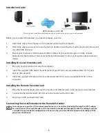
Connecting a USB Device
1.
Install any software required to operate the USB device(s). Refer to the documentation for the USB
device(s), as required.
2.
Connect the USB device to the device port on the Remote Extender unit.
3.
Check that the device is detected and installed properly in the Operating System.
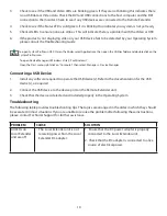
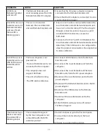
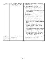
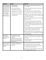
Troubleshooting
The following table provides troubleshooting tips. The topics are arranged in the order in which they should
be executed in most situations. If you are unable to resolve the problem after following these instructions,
please contact Technical Support for further assistance.
PROBLEM
CAUSE
SOLUTION
All LEDs on
Local Extender
unit are off.
• The Local Extender unit is not
receiving power from the Local
Extender DC adapter.
1. Ensure that the DC power adapter is properly
connected to the Local Extender unit.
2. Check that the DC adapter is connected to a live
source of electrical power.
10
note


