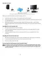
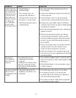
background image

The Remote Extender

The Remote Extender provides DVI output to a monitor, microphone input, headphone output, and three USB 
Type A ports for standard USB devices. Additional devices may be connected by attaching USB hubs.

ITEM

TYPE

DESCRIPTION

1

Device Port (USB Type A)

Accepts USB device(s).

2

Pair (Button)

Reserved. Used if re-pairing a Local Extender to a Remote Extender.

3

Status LED (Green)

LED

 green indicates the system is ready. 

Green

 blinking indicates the 

system is being configured. Off when no power is applied to the unit.

4

Link LED (Green)

LED

 green indicates a valid link is established between the Local and 

Remote Extender. Off indicates there is no link.

5

Video LED 
(Green/Amber)

LED

 green indicates the unit has a valid video link to the monitor and a 

link with the Local Extender. 

Green

 blinking indicates video data is being 

transmitted between the Local and Remote Extender. 

Amber

 indicates 

that there is no monitor connected to the Remote Extender or a monitor 
is not compatible with the system. 

Blinking Amber 

indicates an invalid 

resolution is being detected. Off indicates there is no link between the 
Local and Remote Extenders.

6

USB LED 
(Green/Amber)

LED

 green indicates the system is properly enumerated on the host 

computer. Green blinking indicates USB data is being transmitted between 
the Local and Remote Extenders. 

Amber

 indicates that there is no USB 

connection to the host computer. 

Blinking Amber 

indicates an over 

current condition on one or more of the USB ports. 

Off

 indicates there is no 

link between the Local and Remote Extenders. 

7

DVI-D Out

Accepts DVI-D connector to the remote monitor. 

8

Headphone Out

Accepts 3.5 mm audio connector.

9

Microphone In

Accepts microphone input for audio.

10

Config

Reserved for company use only.

11

Link Port (RJ45)

Accepts RJ45 receptacle for Cat 5 cabling (or better).

12

Power Port

 Connects to the 24V, 1A power adapter 

7

Rear View

Status

Link

Video

US

B

2

1

1

1

3

4

5

6

Pa

ir

24V DC

DVI-D Out

Config

Link

7

8

9

10

11

12

Front View

Summary of Contents for EL4500

Page 1: ...KVM DVI USB 2 0 Cat 5 Extender LAN or 330 feet 100 meters EL4500 User Guide Powered by ...

Page 2: ...equency Interference Statement Warning This device complies with FCC Part 15 Subpart B CE Statement The product meets European Standard EMC EN 55022 Class A EN 61000 and EN 55024 IC Statement This Class A digital apparatus complies with Canadian ICES 003 Information contained herein is subject to change without notice Document 90 00793 A03 ...

Page 3: ...arkings 6 Installation Guide 8 Installing the Local Extender 8 Installing the Remote Extender 8 Connecting the Local Extender to the Remote Extender 8 Checking the Installation 9 Connecting a USB Device 10 Troubleshooting 10 Pairing a Local Extender to a Remote Extenders 14 Specifications 15 Warranty Explanation 16 Contacting Technical Support 16 Technical Glossary 17 ...

Page 4: ...ded with the product A computer with a DVI D DVI I output USB 1 1 or 2 0 compatible computer host computer with a USB compliant Operating System USB 1 1 or 2 0 compatible device s Cat 5 Unshielded Twisted Pair UTP cable with two RJ45 connectors if using surface cabling OR Cat 5 cabling with two information outlets and two Cat 5 patch cords with RJ45 connectors if using premise cabling All referenc...

Page 5: ...ver extended distances Specifications Monitors Samsung Dell HP Viewsonic Acer BENQ ASUS Discrete Graphics Cards NVIDIA ION ATI Radeon HD 2000 Series and Above Matrox P Series Intel GMA 950 and GMA HD NVIDIA Quadro Series ATI FireGL FirePro Series NVIDIA GeForce Mobility 9000 NVIDIA Geforce 6000 Series and Above Resolutions Supported 60Hz 640 x 480 4 3 1280 x 768 5 3 1366 x 768 16 9 800 x 600 4 3 1...

Page 6: ...connected to the Local Extender Blinking Amber indicates an invalid resolution is being detected Off indicates there is no link between the Local and Remote Extenders 5 USB LED Green Amber LED green indicates the system is properly enumerated on the host computer Green blinking indicates USB data is being transmitted between the Local and Remote Extenders Amber indicates that there is no USB conne...

Page 7: ...icates that there is no monitor connected to the Remote Extender or a monitor is not compatible with the system Blinking Amber indicates an invalid resolution is being detected Off indicates there is no link between the Local and Remote Extenders 6 USB LED Green Amber LED green indicates the system is properly enumerated on the host computer Green blinking indicates USB data is being transmitted b...

Page 8: ...er 3 Install the supplied DVI cable to the Local Extender DVI D In and an available DVI Port on the computer Installing the Remote Extender unit 1 Place the Remote Extender unit near the monitor and USB device s in the desired remote location 2 Connect the Remote Extender DVI D Out to the monitor with a DVI cable 3 Plug in your USB and Audio Device s Connecting the Local Extender to the Remote Ext...

Page 9: ...uitable AC outlet near the Local Extender 2 Connect the power adapter to the Local Extender 3 Plug the 24V 1A power adapter into a suitable AC outlet near the Remote Extender 4 Connect the power adapter to the Remote Extender Use only the power adapters supplied with the product Use of substitute adapters may cause permanent damage to the system and will void the warranty Checking the Installation...

Page 10: ...anager in Windows Vista XP or Windows 7 Open the Start menu right click on Computer then select Manage Device Manager Connecting a USB Device 1 Install any software required to operate the USB device s Refer to the documentation for the USB device s as required 2 Connect the USB device to the device port on the Remote Extender unit 3 Check that the device is detected and installed properly in the ...

Page 11: ... or the original Cat 5 cable is defective Link LED on Local Extender unit is on USB LED on Local Extender unit is amber The host computer is not powered on The Local Extender unit is not connected to the computer The computer does not support USB hubs The unit is malfunctioning The USB cable is defective 1 Disconnect all USB devices from the Remote Extender unit 2 Disconnect the Local Extender uni...

Page 12: ...ndows Go to the Control Panel select Sound or Sound and Audio Devices Select USB Audio Devices set USB Audio Devices as default playback b In Mac OS X Go to System Settings select Sound select USB PNP device set USB PNP devices as default c In Linux Ubuntu Go to System Preferences and select Sound To set up the microphone click on the Input tab and select USB_PnP Sound Device Analog Mono To setup ...

Page 13: ...different type to the KVM extender product Connect the KVM extender product to the computer 7 If the second device does not operate the KVM extender product may be malfunctioning Contact Technical Support for assistance 8 If the second device does operate properly the first device may not be compatible with the KVM extender product Microphone or Headphone doesn t operate correctly The audio device...

Page 14: ...er with a Cat 5 patch cable 6 Power the Local Extender and Remote Extender with their corresponding power adapters 7 Hold the Pair button on the front of the Local Extender continuously for 3 to 5 seconds The extender will exchange pairing records During the 3 seconds the Link LED will flash green After pairing the Link LED will turn off 8 Hold the pair button on the front of the Remote Extender c...

Page 15: ... Extender 500 mA each port Local Extender Video Connector DVI D In 24 pin connector USB connector 1 x USB Type B Link connector 1 x RJ45 Dimensions 4 4 x 6 9 x 1 18 112 mm x 175 mm x 30 mm Remote Extender Video Connector DVI D Out 24 pin connector Link connector 1 x RJ45 USB connector 3 x USB Type A Audio 3 5 mm microphone in 3 5 mm headphone out Dimensions 4 4 x 6 9 x 1 18 112 mm x 175 mm x 30 mm...

Page 16: ...ment of hardware which will be warranted for the remainder of the original warranty period or 30 days whichever is longer These remedies are void if failure of the hardware has resulted from accident abuse or misapplication Limitation of Liability The hardware warranty set forth in this agreement replaces all other warranties Icron Technologies Corporation expressly disclaims all other merchantabi...

Page 17: ...e two distinct connectors The Type A connector is used to connect the cable from a USB device to the Type A port on a computer or hub The Type B connector is used to attach the USB cable to a USB device RJ45 The Registered Jack RJ physical interface is what connects the network cabling Cat 5 to the Local Extender unit and Remote Extender unit You may use either the T568A scheme Table 1 or the T568...

Reviews: