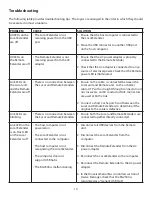
background image

Troubleshooting

The following table provides troubleshooting tips.  The topics are arranged in the order in which they should 
be executed in most situations.  

PROBLEM 

CAUSE

SOLUTION

All LEDs on the 
Local Extender 
are off.

•  The Local Extender is not 

   receiving power from the USB 
   port.

1.  Ensure that the host computer is connected to 
     the Local Extender.

2.  Move the USB connector to another USB port  
     on the host computer.

All LEDs on 
the Remote 
Extender are off.

•  The Remote Extender is not 

   receiving power from the AC 
   adapter.

1.  Ensure that the AC power adapter is properly 
     connected to the Remote Extender.

2.  Check that the AC adapter is connected to a live 
     source of electrical power. Check that the Remote
     power LED is illuminated.

Link LEDs on 
the Local unit 
and the Remote 
Extender are off.

•  There is no connection between


   the Local and Remote Extenders.

1.  Ensure Cat 5e cable  is connected between the
     Local unit and Remote unit.  Cat 5e or better 
     cable, UTP with a straight through connector and 
     no crossovers,  and 8 conductor RJ45 connectors   
     are used at both ends. 

2.  Connect a short Cat 5e patch cord between the 
     Local and Remote Extenders to determine if the 
     original Cat 5e cable is defective.

Link LEDs are 
blinking.

•  There is no connection between


   the Local and Remote Extenders.

1.  Ensure both the Local and Remote Extenders are 
     connected together directly connected.

Link LED on the 
Local Extender 
is on, Host LED 
on the Local 
Extender is off.

•  The host computer is not 

   powered on.

•  The Local Extender is not 

   connected to the computer .

•  The host computer is not 

   recognizing the Local Extender.
  

•  The computer does not


   support USB hubs.

•  The RG2304 is malfunctioning.

1.  Disconnect all USB devices from the Remote 
     unit.

2.  Disconnect the Local Extender from the 
     computer.

3.  Disconnect the Remote Extender from the AC 

power adapter.

4.  Reconnect the Local Extender to the computer.

5.  Reconnect the Remote Extender to the AC power 

adapter.

6.  In the Universal Serial Bus controllers section of 
     Device Manager, check that the RG2304 is 
     recognized as a “Generic USB Hub”.

10

Summary of Contents for RG2304

Page 1: ...USB 2 0 RG2304 4 Port USB 2 0 100m Cat 5e Extender System User Guide ...

Page 2: ...e following two conditions 1 this device may not cause harmful interference and 2 this device must accept any interference received including interference that may cause undesired operation CE Statement We declare under our sole responsibility that the RG2304 to which this declaration relates is in conformity with European Standard EN 55022 EN 55024 EN 61000 3 2 and EN 61000 3 3 IC Statement This ...

Page 3: ...lling the RG2304 System 6 Requirements 6 Preparing Your Site 6 Installing the Local Extender 7 Connecting the Local Extender to the Remote Extender 7 Installing the Remote Extender 7 Checking the Installation 8 Connecting a USB Device 9 Compatibility 9 Troubleshooting 10 Technical Glossary 11 Specifications 12 ...

Page 4: ... Local Extender Remote Extender USB 2 0 Cable Remote Extender AC International Power Adapter Country Specific Power Cable Quick Start Guide Features The RG2304 incorporates ExtremeUSB technology enabling users to extend USB beyond the standard 5m cable limit for USB 2 0 peripheral devices The RG2304 has the following key features 100m of extension when directly connected over Cat 5e Support for ne...

Page 5: ...ote Extenders 3 Host LED Green Indicates that the RG2304 system is properly enumerated on the host computer The LED blinks when the RG2304 is in a suspended state 4 Activity LED Amber Indicates data transmission is occurring between Local and Remote Extender LED blinks intermittently with or without a USB device connected When the Local and Remote Extenders are in suspend mode the LED is off 5 Pai...

Page 6: ...ote Extenders The LED turns on when link between Local and Remote Extenders is established and off when there is no link between Local and Remote Extenders 4 Host LED Green Indicates that the RG2304 system is properly enumerated on the host computer The LED blinks when the RG2304 is in a suspended state 5 Activity LED Amber Indicates data transmission is occurring between Local and Remote Extender...

Page 7: ...f not adjust the location of the devices and or computer accordingly 3 If you are using surface cabling install the Cat 5e cabling as desired and terminate it with the appropriate RJ45 ends If you are using premise cabling ensure Cat 5e cabling is installed between the two locations and if necessary patched together Cat 5e information outlets should be located near the computer and the USB device ...

Page 8: ...e Cabling 1 Connect a Cat 5e patch cable not provided into the information outlet near the host computer 2 Connect the patch cable into the Link port of the Local Extender 3 Connect a Cat 5e patch cable not provided into the information outlet near the USB devices 4 Connect the patch cable into the Link port of the Remote Extender Installing the Remote Extender 1 Place the Remote Extender near the...

Page 9: ... click My Computer then select Properties Hardware tab Device Manager To open Device Manager in Windows 7 or 8 Open the Start menu right click on Computer then select Manage Device Manager 3 For Mac OS X users open the System Profiler to confirm that the RG2304 has installed correctly In the left hand column under Hardware select USB and inspect the right hand panel If the RG2304 has been installe...

Page 10: ... device is detected and installed properly in the operating system Compatibility The USB 2 0 RG2304 complies with USB 1 1 and USB 2 0 specifications governing the design of USB devices However Icron Technologies Corporation does not guarantee that all USB devices or hosts will be compatible with the RG2304 as there are a number of different characteristics that may impact the operation of USB devi...

Page 11: ...t Cat 5e or better cable UTP with a straight through connector and no crossovers and 8 conductor RJ45 connectors are used at both ends 2 Connect a short Cat 5e patch cord between the Local and Remote Extenders to determine if the original Cat 5e cable is defective Link LEDs are blinking There is no connection between the Local and Remote Extenders 1 Ensure both the Local and Remote Extenders are c...

Page 12: ...ects the network cabling Cat 5e to the Local Extender unit and Remote Extender unit You may use either the T568A scheme Table 1 or the T568B scheme Table 2 for cable termination as the USB 2 0 RG2304 requires all four pairs of the cable RJ45 connectors are sometimes also referred to as 8P8C connectors Note that any given cable must be terminated using the same T568 scheme on both ends to operate c...

Page 13: ...ure Material Black Anodized Aluminum REMOTE EXTENDER REX USB Connectors 4 x USB 2 0 Type A Receptacles Link Connector 1 x RJ45 Dimensions 100mm x 76mm x 26mm 3 9 x 3 0 x 1 0 Enclosure Material Black Anodized Aluminum Available Current 600mA at each USB port concurrently Power Supply 100 240V AC input 24V 1A DC Output ENVIRONMENTAL Operating Temperature Range 0 C to 50 C 32 F to 122 F Storage Tempe...

Reviews: