7034 Commerce Circle
Pleasanton, CA 94588
Phone: 925.416.1000
Fax:
925.416.0105
Web: www.icselect.com
Description
4803
GPIB
PARALLEL
DIGITAL INTERFACE
A flexible interface between
the IEEE 488 Bus and
devices with digital signals.
■
Provides a user-definable,
40-line parallel interface with
bit, byte, pulse, string and
binary data transfer capabilities.
Fully configurable to the user's
needs by bus commands.
■
Signal monitor feature allows
the 4803 to detect signal
changes on 15 inputs.
Relieves controller of time
consuming polling operation.
■
High-current drivers and input
pullup resistors.
Drives more devices, longer
lines and inputs CMOS signals
or switch contacts.
■
IEEE-488.2 compatible unit
uses SCPI commands and Short
Form commands.
Includes latest GPIB program
advances
■
Device configuration, user's
IDN message and bus address
stored in Flash.
Stored setup eliminates program
initialization statements.
■
Lock feature prevents accidental
loss or change of user
configuration.
Protects your configuration and
IDN message.
■
Interchangeable with ICS's 2303
Serial and 8003 Ethernet (LAN)
to digital boards.
Easy conversion path.
RoHS Compliant
The Model 4803 GPIB <-> Digital Inter-
face Board is an IEEE-488.2/GPIB to digital
interface with 40 I/O lines that can be used to
easily adapt devices with digital signals to the
IEEE-488/GPIB/HP-IP bus. In a typical applica-
tion, the 4803 is located inside the device and is
powered by the device's +5 volt power supply.
All signal connections can be made with plug-
in flat ribbon cables that directly connect to the
GPIB and digital headers on the 4803. When
used with the companion GPIB Connector/Ad-
dress Switch Board, the 4803 becomes a quick
and easy way to add an IEEE-488.2 interface to
most digital devices.
The 4803 includes a complete manual and
a configuration disk with sample programs. A
Starter kit is available that has everything a non-
GPIB user needs to install a 4803 in his chassis
and control it from the GPIB bus.
Versatile Digital Interface
The 4803's digital interface is configured with
commands from the GPIB Bus. The configuration
commands permit the user to designate the data
lines as inputs and/or outputs in 8-bit byte incre-
ments, connect bytes into strings, set data polarity,
data format, and handshake modes. The user
can set the output lines to his desired values and
save the current configuration in the 4803's Flash
memory. The saved configuration becomes the
new power-on configuration. At power turn-on,
the Digital I/O lines are initially tristated and then
set to the saved configuration. A Stable signal is
asserted after the digital I/O lines are configured
to enable external logic or relays.
IEEE 488/GPIB BUS INTERFACES
Data Transfer Methods
Data transfer between the computer and the
4803's digital interface can be by individual bits,
by bytes or as strings of data values to multiple
bytes as shown in Figure 2.
• Bit commands set or reset specific bits in a
byte or query a bit’s status. New pulse commands
let the user pulse single or multiple output lines
at the same time.
• Byte commands set all 8 bits in a specific
byte or read data from a byte.
• String transfer commands send strings of
data characters to one or more output bytes to
make a multi-byte output word or read a string
of data from one or more input bytes. The user
designates these bytes as inputs or outputs when
configuring the board.
In the Single Address Mode, the user can
set the 4803's configuration and transfer data as
described above. In the Dual Address Mode, the
lower address behaves like the Single Address
Mode. The upper address is used for transparent
data transfer to configured output bytes or to read
data from configured input bytes. The data is sent
or read without having
to parse any commands,
eliminating the parsing
time and speeding up
the data transfer. When
the binary data format
is used, the 4803 can
output data at rates >
50 Kbytes/sec.
4803
IEEE 488 Bus
Controller
Input
Bytes
Output
Bytes
TTL/CMOS
Input Signals or
Contact Closures
High Current
TTL Output Lines
Digital Interface
Host Chassis
Power
Supply
User's
Electronics
IEEE 488 Bus
5 V
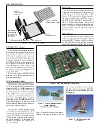
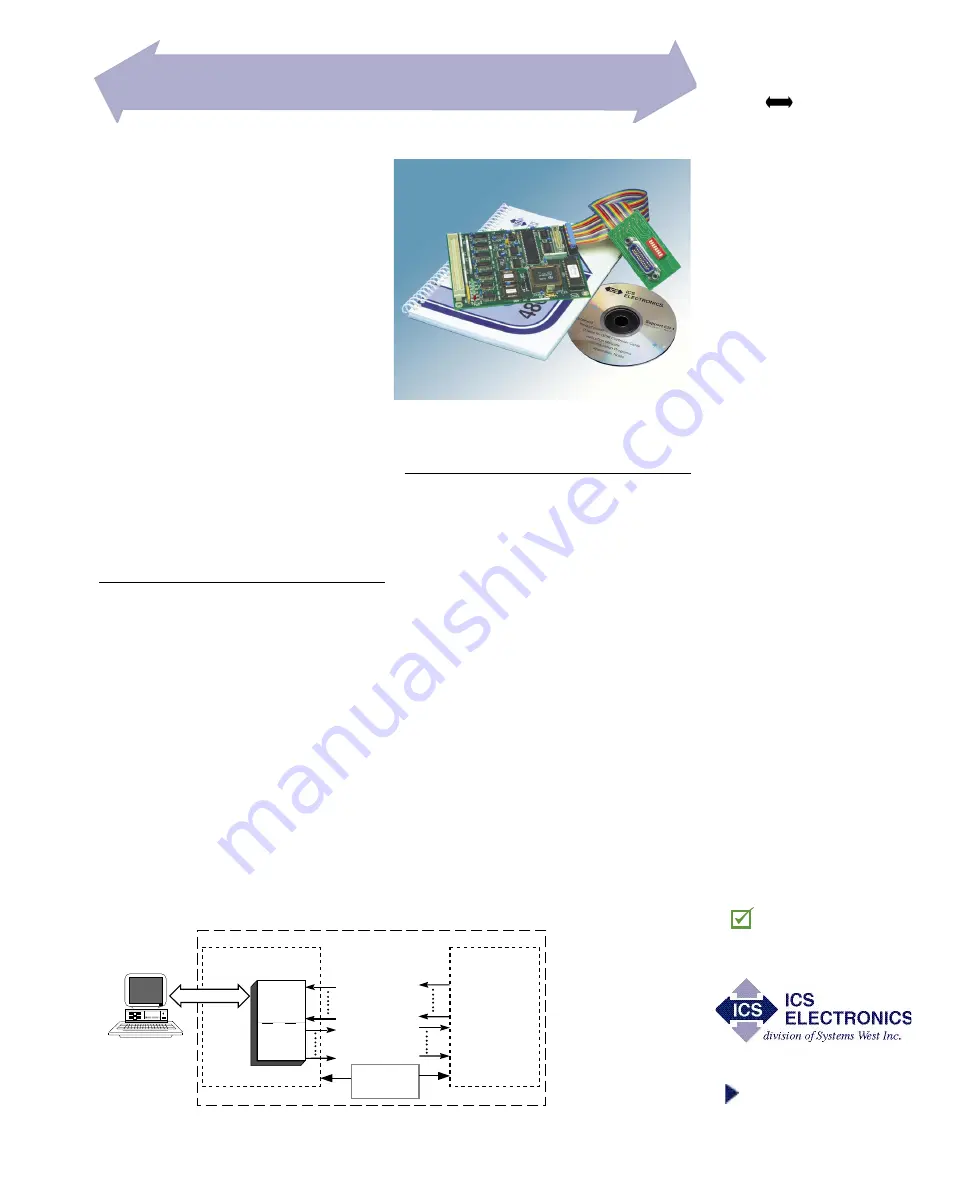
4803 Interface Card and GPIB Connector/Ad-
dress Switch Cable Assembly
Figure 1 A typical 4803 Application


