
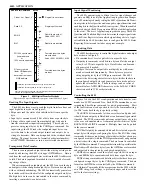
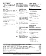
Figure 5 4803 Connection Methods
4803: APPLICATION
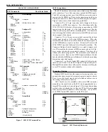
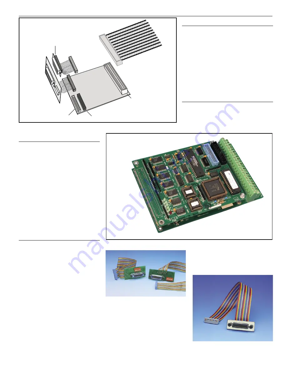
4803 Relay Driver Board
The 4803DVR Board expands the 4803's
drive outputs by providing forty 300 mA relay
drivers with convenient screw terminals. A
4803 with J3 mounted on the circuit side
piggybacks on the 4803DVR board to make
a compact assembly as shown in Figure 6.
The 4803DVR board can be configured for
all 40 lines as relay driver outputs or for
less drivers and for 8 or 16 4803 TTL I/O
lines. The 4803DVR Board is powered by
the relay power supply and it supplies 5 Vdc
power to the 4803.
Refer to the separate 4803DVR Board
data sheet for complete specifications and
mounting dimensions.
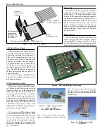
GPIB Connection Cables
ICS offers two styles of the GPIB Connec-
tor/Address Switch Cable Assemblies which
connect the 4803 to a GPIB connector and
Address Switch on the rear panel. Both styles
are business card size, PC board assemblies
with a GPIB connector, metric studs and a 8
position rocker switch. The Address Switch
lets a user set the GPIB address externally
rather than saving the GPIB address in the
4803's flash memory. The two styles of the
GPIB Connector/Address Switch Cable As-
semblies are shown in Figure 7.
ICS also has a GPIB Interface Cable
Assembly that connects the 4803 to a GPIB
connector that mounts on the rear panel of the
chassis. The GPIB connector end includes
two metric studs for mounting the connector
shell to the rear panel. The flat-ribbon cable
assembly is available in any length up to 90
cm. See Figure 8.
114439-L
GPIB Connector
Cable Assy
GPIB Connector-
Address Switch
Board Assembly
P/N 113640-L or
P/N 113642-L
112343 - Open-end
Rainbow Ribbon Cable
Digital
I/O Connector (J3)
GPIB-Address Switch Header (J2)
GPIB Header (J1)
Figure 6 4803 and 4803 Relay Driver Board
Starter Kit
The 4803 Starter Kit provides the OEM de-
signer with everything needed to install and test
a 4803 Board. The Starter Kit includes a 4803
Board, a GPIB Connector/Switch Board Assembly,
the open-end ribbon cable, a GPIB bus cable, a
488-LPCI or 488-USB2 GPIB Controller, ICS's
488.2V3 Drivers and software. The software
package includes a keyboard command line pro-
gram, a Visual Basic configuration program and
example programs. There is a limit of one Starter
Kit per customer.
4803 SDK Kit
The 4803SDK Kit provides everything a user
needs to write custom 4803 programs. The kit
contains the IAR 'C' language compiler, spy debug-
ger, ICS's SDK library disk, manual and spare flash
chips. ICS's library disk contains the SCPI parser
Figure 7 GPIB Connector/Address
Switch Assemblies
P/N 113642-L and P/N 113640-L
Figure 8 GPIB Interface Cable
P/N 114439-L
files, 'C' routines, make files and example
4803 files. Refer to the separate 4803SDK
data sheet for more information about the
SDK package.
Note: '-L' in the cable assembly part numbers
stands for cable length in cm from 10 to 90 cm.


