

IEEE 488 Bus Interface
The 4803's 488 Bus interface meets IEEE
STD 488.1-1987 and has the following ca-
pabilities:
SH1, AH1, T6, L4, SR1, PP0, DC1,
RL0, DT1, C0 and E2 drivers.
Address Capability
Dual primary addresses or single primary
with secondary addresses 00 and 01. Primary
address range: 0-30.
SRQ Generation
SRQs are generated if the unit is not a talker,
if SRQs are enabled and if an Enabled Event
Status Register bit or an monitored digital input
change occurs. Digital inputs monitored by the
Questionable registers.
488.2 Common Commands
*CLS, *ESE, *ESE?, *ESR?, *IDN?, *OPC,
*OPC?, *RCL, *RST, *SAV, *SRE, *SRE?,
*STB, TST? and *WAI
SCPI Commands
Used to set and query all programmable func-
tions. The 4803 conforms to SCPI 1994.0
Specification.
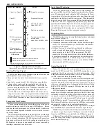
4803: SPECIFICATIONS
Signal Characteristics
The 4803's parallel I/O signals have the follow-
ing electrical characteristics. All time delays
listed here are maximums, all pulse widths
are minimums.
Inputs
40 Digital I/O ,
2 Status and Reset Inputs
Input
High = > +2.0 V @ ±10 µA
Max High = 5.5 V
Logic
Low = <0.8 V @ 250 µA
Levels
with 33 Kohm pullup to +5 Vdc
for sensing contacts.
Input
External Data Inhibit line
Timing SETS within 1 µs of the active edge
of the EDR Input signal and resets
after data is loaded. Data loading
time for 6 BCD/HEX characters is
0.15 ms (typ.) after the 4803 has
been addressed as a Talker
Output High = >3 V with 3 mA source
Logic
High =>2 V with 24 mA source
Levels
Low = 0.0 to +0.55 Vdc, 48 mA
sink
Output Data is transferred to the
Timing output 0.6 to 5.3 ms after receipt of a
terminator depending upon transfer
method.
Pulse width 10 to 30000 ms
Data Stb Output pulse width, 5 µs
Trigger Output pulse width, 5 µs
Remote Output level asserted when in the
remote state
Reset
Output pulse width, 40 µs for
*RST command and true during
4803 reset time (70 ms)
Stable Output level asserted when Digital
I/O lines have been configured.
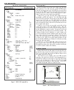
Diagnostic Indicators
Six on board LEDs with drive signals on the
DIN connector for remote LEDs
PWR, RDY, TALK, LSTN, SRQ and
ERR
Physical
Size, L x W x H
139.7 x 114.3 x 14.3 mm
(5.5 x 4.5 x 0.562 inches)
Connectors and Headers
GPIB: 24-pin 3M 2524 male conn.
GPIB/Addr: 26-pin 3M 2526 male conn.
Digital I/O: 96-pin, 3 row male DIN
conn using rows A & C.
Temperature
Operation
-10° C to +70° C
Storage
-20° C to +85° C
Humidity
0-90% RH without condensation
Power
+5 Vdc @ 400 mA (typical)
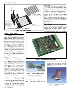
Included Accessories
Instruction Manual
Configuration Disk with sample programs
Available Accessories
See the Ordering Guide on page 4 for a complete
list of accessory items.
GPIB flat ribbon cable 90 cm max.,
P/N 114439-90.
GPIB Connector/Addr Sw Assy with flat
ribbon cable, 90 cm max., P/N 113640-90
or P/N 113642-90.
See the GPIB Conn/Sw data sheet.
Open-end rainbow ribbon cable, 5 ft,
P/N 112343
Mating DIN Connectors:
P/N 902023 Solder Eyelet
P/N 902067 Dip Solder
P/N 902124 Flat ribbon Cable
ORDERING INFORMATION
Part Number
IEEE 488.2 to Parallel Digital Interface Board (Includes Instruction Manual and Configuration Disk)
4803
IEEE 488.2 to Parallel Digital Interface Board (Board only)
114642
4803 Starter Package with 4803, 488-LPCI card, Bus Cable, GPIB Connector/Switch Bd, and Connectors
114646-01
4803 Starter Package with 4803, 488-USB2 Controller, Bus Cable, GPIB Connector/Switch Bd, and Connectors
114646-02
4803 with connector on circuit side (Includes Instruction Manual and Configuration Disk)
114648
4803 with connector on circuit side (Board only)
114649
GPIB Connector/Address Switch Assemblies
see separate data sheet
GPIB Flat Ribbon Cables
see separate data sheet
Open-end Rainbow colored flat ribbon cable, 5 feet long
112343
Copyright 2010 ICS Electronics - Specifications subject to change without notice.
04/10


