ICStation RGB LED Bluetooth Amplifier Christmas Tree DIY Kit
orders@icstation.com
3
7.Installation Tips:
1>.User needs to prepare the welding tool at first.
1.1>.Soldering iron (<50 Watt)
1.2>.Rosin core ("radio") solder
1.3>.Wire cutters
1.4>.Wire strippers
1.5>.Philips screwdriver
2>.Please be patient until the installation is complete.
3>.The package is DIY kit.It need finish install by user.
4>.The soldering iron can't touch the components for a long time(3s), otherwise damage
components.
5>.Pay attention to the positive and negative of the components.
6>.Strictly prohibit short circuit.
7>.User must install the LED according to the specified rules.Otherwise some LED will not light.
8>.Install complex components preferentially.
9>.Make sure all components are in right direction and right place.
10>.Check that all of the LED can be illuminated.
11>.It is strongly recommended to read the installation manual before starting installation!!!
12>.Please wear anti-static gloves or anti-static wristbands when installing electronic
components.
8.Installation Steps(
Please be patient
):
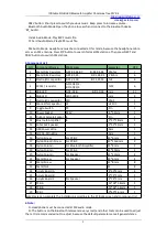
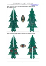
Step 1: Install 7pcs 100ohm Metal Film Resistors at R2,R4,R6,R7 on PCB-A and R2,R4,R6 on
PCB-A.
Step 2: Install 6pcs 4.7Kohm Metal Film Resistors at R1,R3,R5 on PCB-A/B.
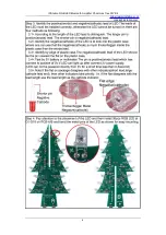
Step 3: Identify the positive(anode) and negative(cathode) lead of LED.The leads of the LED
must be installed correctly, otherwise the LED cannot be turned on.Here are four methods as
following:
3.1>.According to the length of the LED lead to distinguish. The longer pin is positive(anode)
lead. The shorter pin is negative(cathode) lead.
3.2>.Identify the negative(cathode) of the LED is to look into the plastic case where one can
see that the negative(cathode) is much thicker/bigger inside the plastic case than the anode
lead.
3.3>.Identify by edge of plastic case.The negative(cathode) lead of the LED should be the pin
nearest the flat on the plastic case.
3.4>.Test by 3V battery or multimeter.The pin is positive(anode) lead which has connect to
the positive of 3V if LED can light up after connect 3V power supply.(LED should not be
powered directly from the 3V for a short time:less then 0.5second)
3.5>.It is positive(anode) where the white mark “ + ” pointing to on PCB.
Step 4: Pay attention to the placement of the LED and then install 36pcs RGB LED at D1-D18 on
PCB-A/B and bend the metal pins of the LED as shown for easy mounting.
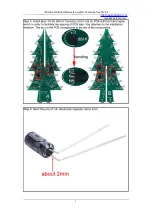
Step 5: Install 6pcs TO-92 S9014 Transistor at Q1,Q2,Q3 on PCB-A/B then bend again which in
order to facilitate the splicing of PCB later. Pay attention to the installation direction. The arc on
the PCB corresponds to the arc of the components.
Step 6: Bend the pins of 1uF electrolytic capacitor about 2mm.
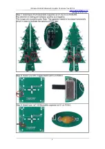
Step 7: Install 6pcs 47uF Electrolytic Capacitor at C1,C2,C3 on PCB-A/B. Pay attention to
distinguish between positive and negative. The Longer pin is positive pole. Note: The capacitor
needs to be placed horizontally which in order to facilitate the splicing of PCB later.
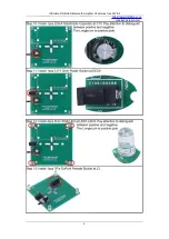
Step 8: Install 1pcs 5Pin Toggle Switch at P2 on PCB-C.


