65
7.
Troubleshooting
7.1.
Error Code Messages
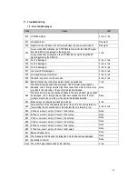
Code
Cause
LED
E10 LCM Panel Open
5 red + 2 red
E11 Checksum Error
Red Light
E12 Signal from the coin base was not received when the power was turned on.
Red Light
E13
Two seconds after activation, the SYSTEM did not wait for the READY signal
from the DEVICE and jumped to the exception.
1 red
Two seconds after a transaction, the SYSTEM did not wait for the READY
signal triggered by the DEVICE.
E14 Coil 1 is damaged.
3 red + 1 red
E15 Coil 2 is damaged.
3 red + 2 red
E16 Coil 3 is damaged.
3 red + 3 red
E17 Low level LED is damaged.
3 red + 5 red
E18 Coin separator sensor problem.
3 red + 4 red
E19 The deck is open for over 30 seconds.
5 red + 1 red
E20 Both the first and second group motors cannot be positioned.
7 red
E21
The first motor group cannot be positioned. The first motor group might be
damaged, coin or foreign objects might have caused the motor to stuck, coins
are stuck in the coin tube, or the semicircle disk has derailed.
None
E22
The second motor group cannot be positioned. The second motor group might
be damaged, coin or foreign objects might have caused the motor to stuck,
coins are stuck in the coin tube, or the semicircle disk has derailed.
None
E23 Broke away or incorrectly positioned coin tubes.
5 red
E24
Coins got stuck at the coin separation area or the coin tube opening twice in a
row, causing the HI Level Sensor to fail to detect the coin twice in a row.
6 red + 4 red
E25 A Tube Low Level = empty, HI Level = full at setup.
None
E26 B Tube Low Level = empty, HI Level = full at setup.
None
E27 C Tube Low Level = empty, HI Level = full at setup.
None
E28 D Tube Low Level = empty, HI Level = full at setup.
None
E29 E Tube Low Level = empty, HI Level = full at setup.
None
E30 F Tube Low Level = empty, HI Level = full at setup.
None
E31 Barcode Reader Error
None
E32 The three sets of LEDs used to distinguish Coin size have been damaged.
None
E33 Recosnition Ver Error
None
None The „Inhibit“ signal transmitted by the interface.
2 red
Summary of Contents for cc6000
Page 1: ...1...
Page 7: ...7 1 3 Dimensions Unit mm Mounting position Vertical max deviation 3 Mark of conformity CE FCC...
Page 9: ...9 Coin Tubes Press the latch as shown below to remove the coin cassette...
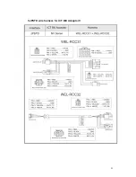
Page 49: ...49 4 3 Wire Harness Pin Assignment for JPSTD interface Main wire harness...
Page 50: ...50...
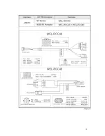
Page 51: ...51 JPSTD wire harness for ICT Bill Acceptor...
Page 52: ...52...
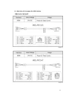
Page 53: ...53 4 4 Wire Harness Pin Assignment for MDB interface Main wire harness...
Page 54: ...54...
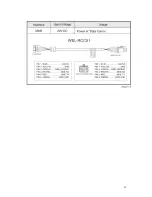
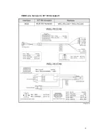
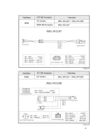
Page 55: ...55 MDB wire harness for ICT Bill Acceptor...
Page 56: ...56...
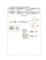
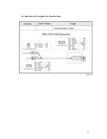
Page 59: ...59 4 6 Wire Harness Pin Assignment for Download Box...
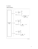
Page 60: ...60 5 I O Circuit JPSTD Interface...
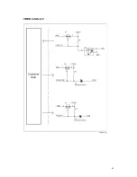
Page 61: ...61 MDB Interface...
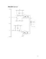
Page 62: ...62 Executive Interface...
Page 64: ...64...

