92
11.
Module Assembling Procedure
11.1.
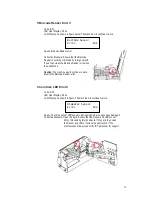
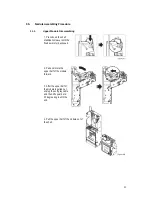
Upper Module Disassembling:
1. Press down the shell
stabilization leaver until the
fixed axis is fully exposed.
2. Pull and rotate the
upper half of the module
forward.
3. After the upper half of
the module is pulled out,
unplug the soft gray cable,
and then lift upward at a
35 degree angle until the
end.
4. Pull the upper half of the module out of
the shell.
Summary of Contents for cc6000
Page 1: ...1...
Page 7: ...7 1 3 Dimensions Unit mm Mounting position Vertical max deviation 3 Mark of conformity CE FCC...
Page 9: ...9 Coin Tubes Press the latch as shown below to remove the coin cassette...
Page 49: ...49 4 3 Wire Harness Pin Assignment for JPSTD interface Main wire harness...
Page 50: ...50...
Page 51: ...51 JPSTD wire harness for ICT Bill Acceptor...
Page 52: ...52...
Page 53: ...53 4 4 Wire Harness Pin Assignment for MDB interface Main wire harness...
Page 54: ...54...
Page 55: ...55 MDB wire harness for ICT Bill Acceptor...
Page 56: ...56...
Page 59: ...59 4 6 Wire Harness Pin Assignment for Download Box...
Page 60: ...60 5 I O Circuit JPSTD Interface...
Page 61: ...61 MDB Interface...
Page 62: ...62 Executive Interface...
Page 64: ...64...

