12
Innovative Circuit Technology Ltd.
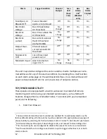
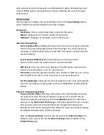
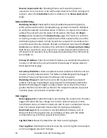
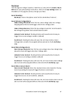
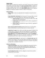
Alarm
Trigger Condition
Channel
Output
Fuse
LED
(Fuse
vers)
Bus
Alarm
LED
1
(Breaker
vers)
Bus
Alarm
Contact
1
Fuse Open, or
Breaker Off
Fuse or breaker
opens or is removed
Off
On
On
On
Bus Under-
voltage
Bus V drops below
UV threshold
No
change
2
Off
On
On
Bus Over-
voltage
Bus V rises above the
OV threshold
No
change
Off
On
On
Bus Over-
current
Bus current exceeds
the OC threshold
(default 100A)
No
change
Off
On
On
Output Over-
current
Channel output
current exceeds OC
threshold
Off
3
Off
On
On
No power to
Unit
Loss of bus input
power source
Off
Off
Off
On
Site Alarm Input Alarm contact on
input 1 to 5
No
change
No
change
On
On
4
The unit may also be configured to send an alarm e-mail to multiple user set e-
mail addresses for any of the alarm conditions, by enabling the e-mail function
on each alarm setup page on the web based interface. (no e-mail will be sent if
power is disconnected from the unit, due to loss of network control)
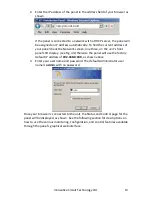
TCP/IP WEB BASED UTILITY
These panels are equipped with a built in web server to enable full remote
monitoring and control using any standard web browser, such as Microsoft
Explorer, Google Chrome, or Mozilla Firefox. To connect with your networked
panel, do the following:
1.
Start Your Browser.
1
The Bus Alarm LED and Bus Alarm contact are enabled for Fuse/Breaker alarms as the
factory default setting; all other alarms must be enabled in the appropriate setup page of
the web utility by selecting the “Activate Alarm Form C Contact” check box for each alarm.
2
All channel relays will be open if Bus Voltage is <6V, and recover for Bus Voltage >8V
3
The channel may be user configured to disable the output for an Over-current Alarm
4
Use the web interface to configure each alarm input to trigger either Bus A, B or both
alarm contacts


