14
Innovative Circuit Technology Ltd.
Click on any one of the blue buttons in the menu bar on the left side of the
screen to select the desired page.
Status and Control
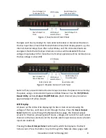
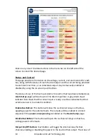
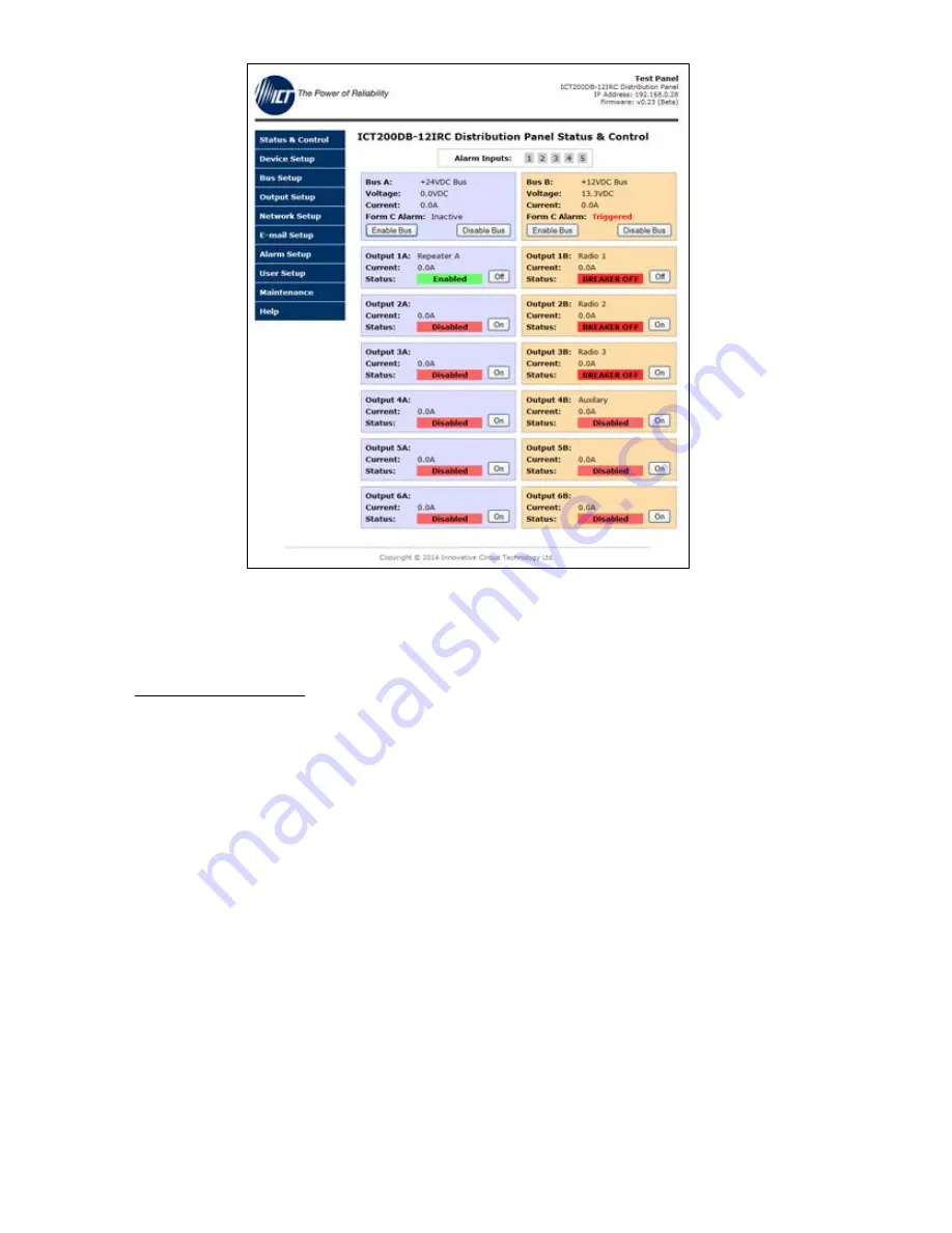
This page provides information on the voltage, current, and alarm status for each
bus, along with the status of each channel output and the current being provided
to each load. Each bus, or an individual output may be manually enabled or
disabled by using the on screen push buttons.
The status of any of the five Input Alarms for alarms that have been enabled (see
Alarm Setup
page) will be shown in the Alarm Input box. A grey Alarm Input
indicator box shows that the sensor input is ready; a red box indicates that that
external sensor is in an alarm condition.
Enable Bus Button:
This button will close the six channel relays on that bus,
applying power to the external loads. The outputs will be enabled in a timed
sequence if the
power-on sequencing
is enabled on the
Device Setup
page.
Disable Bus Button:
This button will open the six channel relays on that bus,
cutting power to the loads.
Output On/Off Buttons
: Each button will toggle the internal relay for that
channel, enabling or disabling the power to the load on that output. The status of


