

Innovative Circuit Technology Ltd.
15
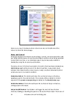
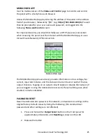
each output channel is shown with a red (Disabled) or green (Enabled) bar next
to the ON/OFF button, along with an ammeter indicating the current through
that channel.
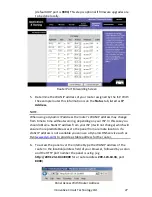
Device Setup
Use this page to configure the panel settings. Click on the
Save Settings
button
when finished to save and implement all new changes.
Device Info
Site Name
: Enter a custom descriptive name for the panel
Model:
Displays the ICT model number for the panel
Hardware
: Displays the hardware version of the panel
Date and Time Settings
Current System Time
: Displays the date and time used in the panel’s internal
clock for time stamping data entries in the data logs. This clock may be set
manually, or synchronized with a remote NTP Time Server over the Internet
(recommended).
Synchronize with NTP Server
: Check this box to select automatic
synchronization with the external server. (recommended)
NTP Server
: Enter the name or IP address of the NTP Server used for date
and time synchronization, such as “
pool.ntp.org”
.
Time Zone
: Select the appropriate time zone relative to GMT for your unit so
that the NTP server time can be converted to your local time zone.
Set Time Manually
: Checking this box will allow the unit’s clock and calendar
to be set manually by entering date and time in MM/DD/YY and HH:MM:SS
format.
Power-On Sequencing/Cycling
Sequence/Cycle Delay
: Entering a time delay in this field (0-60s) will cause
the outputs on each bus to be enabled in sequence (1 to 6) with the set
delay time between each step, when the
Enable Bus
button for that bus is
pressed on the
Status and Control
page. This helps reduce the turn-on surge
that can occur when all connected loads are energized simultaneously.
Setting this time to 0 or leaving the box blank will cause all outputs to always
be enabled simultaneously. (Factory default)
Note the
Sequence Delay
time will also be used as the
Power Cycling
time
delay for each output that has the
Power Cycling
feature enabled on the
Output Setup
page.


