background image

6


Innovative Circuit Technology Ltd.


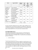
Ensure the total power consumption of the loads does not exceed the 80A 

(continuous) rated capacity of each power bus 


Channel output breakers or fuses must not exceed 25A max rating for 

12/24VDC systems, 15A max for nominal 48VDC systems 


Install only 80VDC rated fuses, 15 A max each for nominal 48Vdc systems 


Install only 65VDC rated breakers, 15 A max each for nominal 48Vdc systems 


Do not block air inlet or outlet openings in the panel sides 


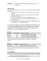
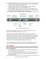
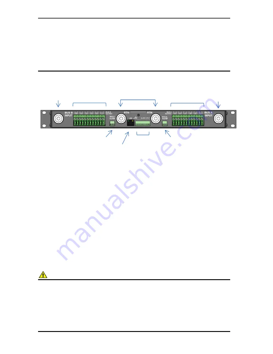
Figure 1: Back Panel Connections 


Mount the Dual Bus Distribution Panel in a 19 inch equipment rack, using 

standard rack mounting hardware. (Not provided) 


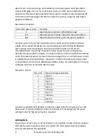
On breaker equipped models install appropriately rated circuit breakers in 

desired channel locations by carefully inserting a breaker so that its mounting 

tabs securely snap into the front panel. Install the breaker blanking plugs in any 

unused locations. Breakers and plugs may be removed by using two small 

screwdrivers or similar tools to press in the top and bottom mounting tabs 

through the cover openings and gently prying out of the panel. 


On fuse equipped units change any channel fuses requiring different current 

ratings. (Up to 25A max on 12 or 24V systems, 15A max on 48V systems) 


WARNING 

Risk of serious personal injury or damage to equipment and property! Always 

observe the following: 


Use an appropriately rated over-current protection device in line with the 

main battery connections  to the panel  


Use an appropriately rated disconnect switch or circuit breaker in line with 

the dc inputs to enable installation and service of the panel with the dc 

source disconnected 

Bus A Outputs 

Channel 1-6 

Bus B Outputs 

Channel 1-6 

Bus A/B Input RTN 

Connectors (common) 

Bus B Input 

(100A max) 

Bus A Input 

(100A max) 

Site Alarm 

inputs 1-5 

Bus A Alarm 

out 

C/NC/NO 

Bus B Alarm 

out 

C/NC/NO 

LAN Port 

10/100


Base-T


Summary of Contents for ICT200DB-12IRC

Page 1: ...Innovative Circuit Technology Ltd Dual Bus Distribution Panel Series INSTRUCTION MANUAL 855 314 000 Models ICT200DF 12IRC ICT200DB 12IRC...

Page 2: ...e or circuit breaker and keep cable lengths as short as practical Carefully observe wiring polarity when making input and output connections Securely tighten all connections Do not attempt to service...

Page 3: ...11 TCP IP WEB BASED UTILITY 12 Status and Control 14 Device Setup 15 Bus Setup 17 Output Setup 18 Network setup 19 E mail Setup 21 Alarm setup 23 User Setup 23 Maintenance 24 MOBILE WEB APP 25 PASSWO...

Page 4: ...ion allows full access to channel configuration settings provides remote channel on off control and can be set up to send an alarm to user defined email accounts in the event a fault occurs The web se...

Page 5: ...e Twelve 15A 80VDC FKS ATO blade fuses are shipped with each ICT200DF 12IRC panel while circuit breakers need to be ordered separately per the following list for use on the ICT200DB 12IRC panel Breake...

Page 6: ...nt panel Install the breaker blanking plugs in any unused locations Breakers and plugs may be removed by using two small screwdrivers or similar tools to press in the top and bottom mounting tabs thro...

Page 7: ...but must share a common RTN voltage normally at earth potential Connect the main Bus A RTN line to the external battery or power supply return using wire and ring connectors rated for up to 100A cont...

Page 8: ...tacts must be voltage free as a small sense current is supplied from the panel Alarm Input pins to detect the external contact open or closed state Refer to the Web Based Utility section for informati...

Page 9: ...tons Each channel relay consumes approximately 1W when closed LCD Display At power up the LCD will be displaying the Bus A main screen showing the voltage of that bus and total current through the bus...

Page 10: ...ll blink if the voltage exceeds the Under voltage or Over voltage alarm thresholds Line 4 Total bus current current will blink if the bus current exceeds the Over current alarm threshold Network Scree...

Page 11: ...s Alarm contacts on the back are used to indicate an alarm condition BUS A MENU BUS B MENU BUS A BUS B SYS VOLTAGE 13 80V SYS VOLTAGE 51 2V BUS CURRENT 76 4A BUS CURRENT 32 5A 100 Base T 100 Base T 18...

Page 12: ...abling the e mail function on each alarm setup page on the web based interface no e mail will be sent if power is disconnected from the unit due to loss of network control TCP IP WEB BASED UTILITY The...

Page 13: ...he unit s front panel LCD display see Fig 4 Otherwise the panel will use the factory default IP address of 192 168 0 180 as shown above 3 Enter your user name and password The default Administrator us...

Page 14: ...at have been enabled see Alarm Setup page will be shown in the Alarm Input box A grey Alarm Input indicator box shows that the sensor input is ready a red box indicates that that external sensor is in...

Page 15: ...NTP Server Enter the name or IP address of the NTP Server used for date and time synchronization such as pool ntp org Time Zone Select the appropriate time zone relative to GMT for your unit so that...

Page 16: ...IP address you would like the panel to monitor If left blank the unit will monitor the Gateway IP address listed in the Network Setup page Secondary IP Address Enter an optional second IP address that...

Page 17: ...this box will cause the unit to send a Bus Under Voltage alarm e mail to the assigned address entered on the E mail Setup page Bus A B Over Voltage Alarm Over Voltage Threshold Enter the bus over volt...

Page 18: ...Will mask the fuse or circuit breaker open circuit detection to prevent false alarms on unused channels Enable Power Cycling Check this box to enable output power cycling for the selected output so th...

Page 19: ...ondition Send E mail Checking this box will cause the unit to send an output Over Current alarm e mail to the assigned address entered on the E mail Setup page Disable This Output Check this box to au...

Page 20: ...HTTP port is 80 and if you change this the new HTTP Port number must be appended to the URL used to access the panel e g use URL http 192 168 0 180 8000 for IP address 192 168 0 180 port 8000 HTTPS Po...

Page 21: ...t with all traps Some trap receivers are able to filter based on Trap Community Trap IP Addresses Assign the IP address for up to two devices that will receive SNMP traps from the panel Enable SNMP Wr...

Page 22: ...SMTP Password Enter a SMTP password here if required by your SMTP server Leave this field blank if the server does not require authentication Minimum E mail Interval Specify a minimum interval require...

Page 23: ...t closure events on door and window sensors smoke alarms etc Alarm Name Enter a descriptive name for the external contact being monitored This will be used in e mail and front panel alarm messages Con...

Page 24: ...o confirm the new password changes prior to saving the settings Maintenance Use this page to reset the panel soft reset restore the panel default settings or send a test e mail to verify e mail functi...

Page 25: ...App or use a Virtual Private Network VPN connection Mobile Web App The Mobile Web App shown above provides information on bus voltage bus current input alarm status and the status and current level of...

Page 26: ...cation field b Enter the HTTP port number that the panel is using in the Start and End fields The default HTTP port for the panel is 80 c Select Both under Protocol TCP and UDP d Enter the local IP ad...

Page 27: ...epending on your ISP In this case you should obtain a Static IP address from your ISP it will not change which will ensure more predictable access to the panel from a remote location If a static IP ad...

Page 28: ...lity cellnumber txt bell ca Rogers cellnumber pcs rogers com Telus cellnumber msg telus com Virgin Mobile Can cellnumber vmobile ca TROUBLESHOOTING I am unable to access the web based configuration ut...

Page 29: ...l Verify that the Send E mail checkboxes are ticked for any alarm conditions for which you wish to receive e mail notifications Verify your e mail settings by going to the Maintenance page on the pane...

Page 30: ...DB 25A Max 65Vdc x 6 per bus 12 24V 15A Max 65Vdc x 6 per bus 48V CAUTION Use only 65Vdc rated breakers 15A max each for nominal 48Vdc systems or 25A max for 12 or 24V systems NOTE Breakers should nor...

Page 31: ...AWG 5 22in lb Alarm Connectors Removable plug cage clamp type 16 28 AWG 1in lb screw torque Operating Temperature 20 C to 60 C Derate max bus current by 2 per degree C above 50 C Weight 7 lbs 3 2kg Wa...

Page 32: ...otional materials accurately describe ICT product specifications and capabilities at the time of publication However because of ongoing improvements and updating of ICT products ICT cannot guarantee t...

Reviews: