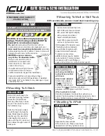
ELITE 5220 & 5216 INSTALLATION
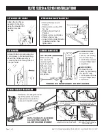
EASY-TO-CABLE-MANAGE ELITE 5220 & 5216 INSTALLATION - 11/13/17
Page 3 of 3
The rotation limits for the arm
are set by placing the stop pins
in the holes corresponding to
where you want the arm to
stop. The stop pin then bumps
into the stop block on the front
of the wall mount ear, stopping
the arm. The stop pins can be
removed and set by hand.
Stop Pin
Stop Block
MONITOR TILT, ROTATION & ADJUST MONITOR DEPTH
MONITOR TILT
& ROTATE
Gently hold sides
of monitor. Tilt and
rotate to desired
position with ball
VESA.
ADJUST
MONITOR
DEPTH
Loosen the
adjustment
knob, move
the Paralink
forward or
back, then
re-tighten
the knob.
Adjustment
Knob
ADJUST ARM LIFTING CAPACITY
ADJUST ROTATION LIMITS - WALL MOUNT
Stop Pin
If foot of Elite is not level:
•
Remove long top cover
and front end cover.
•
Insert 9/16 socket wrench over nut in end frame.
•
From beneath arm, slightly
loosen center bolt with
provided hex key.
•
Tighten set screws with
hex key until foot is level,
then
retighten center bolt
.
Check for level. Repeat if
necessary. If center bolt is
not retightened, the Elite foot
could come loose.
•
Replace arm covers.
9/16
socket
wrench
End
frame
REATTACH ARM COVERS
TOP COVERS:
Reattach by replacing the two 6-32 x
1/4” flathead screws in the center of the cover using a
Phillips head screwdriver.
CENTER COVER:
Reattach by replacing the four
10-24 x 3/4” flathead screws using a Phillips head
screwdriver.
END COVERS:
Reattach by replacing the two 10-24 x
3/4” flathead screws using a Phillips head screwdriver.
ADJUST BALL VESA TENSION & HEIGHT
Pivot tension
adjustment screws
Use the slider knob
to loosen the slider
to adjust the height
of the monitor on the
Paralink.
Adjust the pivot tension
of the ball by gently
and evenly tightening
or loosening the four
screws on the back of
the ball VESA.
Slider knob
Extend the arm straight out as shown
before adjusting the arm’s lifting
capacity. Be sure all equipment is
mounted on the arm before
adjusting. Adjust the arm
closest to the monitor
first. Use the T-handle
provided.
DO NOT USE
POWER TOOLS TO ADJUST
Button
head bolt
Set
screws
ADJUST HORIZONTAL TILT ANGLE


