If you have any questions, please call 1-800-558-4435
ERGOVISION 65 INSTRUCTIONS
ERGOVISION 65 INSTRUCTIONS - rev 04/22/14 pjm
Page 2 of 2
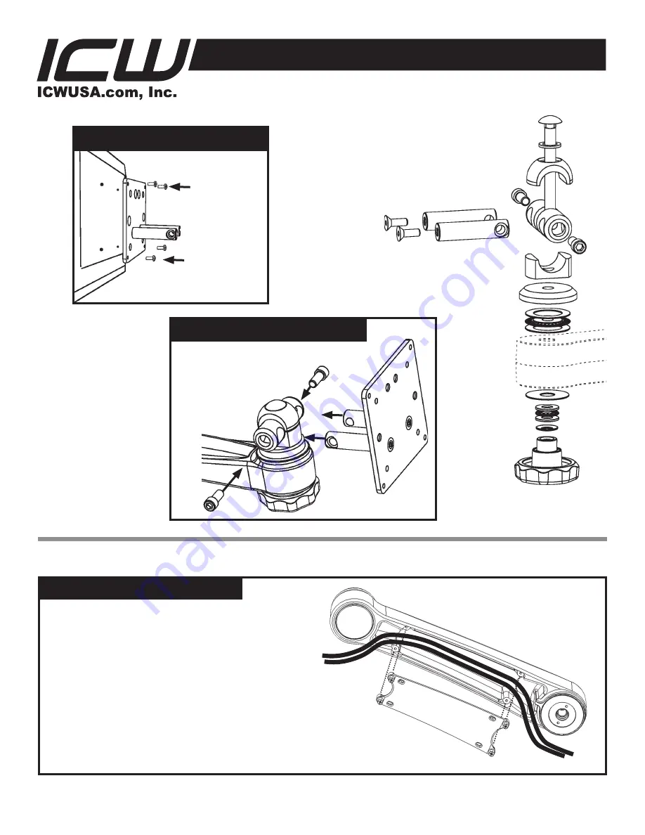
ATTACH VESA TO EV65 JOINT
Socket
cap screw
VESA
plate
Insert stubs on VESA plate into
holes in the Ergovision joint
assembly. Insert 5/16 x 3/4
socket cap screws provided in
both sides and tighten. Use the
handle under mount
to loosen tilt friction
and adjust monitor
tilt.
ATTACH VESA TO MONITOR
Attach the
monitor mount
assembly to
the back of
your monitor,
using the
4mm screws
provided.
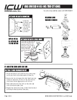
ULTRA CORD MANAGEMENT
1. Prepare all cables to route within the arm by placing them
near cavity of arm and bundling together if necessary.
2. Remove cover by unscrewing four socket head cap screws.
Screws are captured by the cover so they cannot fall out.
Once screws are disengaged, pull cover out of arm.
3. Place cables within the channel. Do not block the holes
where screws will engage in arm.
4. Replace cover and tighten screws. Cables should be able to
pull through to desired position if necessary.
AFTER VESA
IS ATTACHED
TO MONITOR
IF AN EXTENSION ARM IS USED
BEARING AND
WASHER ORDER


